Difference between revisions of "Tugas Besar Metode Numerik - Josiah Enrico S"
JosiahEnrico (talk | contribs) (→Procedure) |
JosiahEnrico (talk | contribs) (→Procedure) |
||
| Line 47: | Line 47: | ||
'''Koleksi Data''' | '''Koleksi Data''' | ||
| − | <gallery | + | <gallery widths=400px style="text-align:center"> |
Tugas Besar Metnum Dimension Jos.jpg|300px|'''Table 1''' Angle bar standard dimension and area | Tugas Besar Metnum Dimension Jos.jpg|300px|'''Table 1''' Angle bar standard dimension and area | ||
Tugas Besar Metnum Sample Jos.jpg|300px|'''Table 2''' Cost of material in market | Tugas Besar Metnum Sample Jos.jpg|300px|'''Table 2''' Cost of material in market | ||
Revision as of 14:48, 13 January 2021
Contents
Abstract
Introduction
Objective
- Membuat program analisis truss dan optimasi sederhana dengan Modelica
- Mengoptimasi harga pembuatan rangka truss sederhana dengan memvariasi dimensi dan elastisitas material.
Methodology
- Metode Optimasi Golden Section (univariabel)
- Metode Optimasi Golden Section (multivariabel)
Procedure
Geometri dan Load
| F1 | 2000 |
|---|---|
| F2 | 1000 |
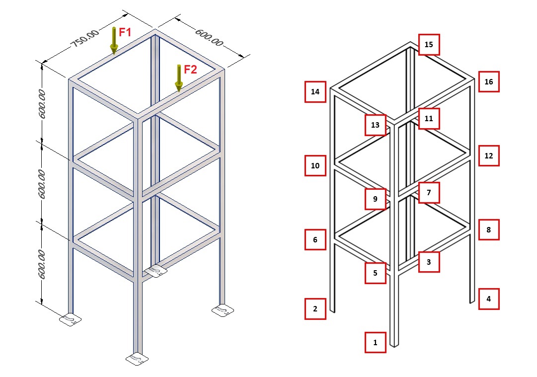
Figure 1 Truss geometry and load

Constraint:
- Spesifikasi L (Panjang) dan geometri rangka truss
- Gaya beban terhadap struktur (1000 N dan 2000 N)
Asumsi:
- Beban akan terdistribusi hanya pada point penghubung dan semua gaya yang dipengaruhi moment diamggap tidak ada karena sistem bersifat truss
Koleksi Data
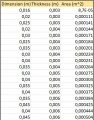
Table 1 Angle bar standard dimension and area

Table 2 Cost of material in market


Data Proceessing

model Truss_3D_Tugas_Besar_Safety
// Base Code by Josiah Enrico S. 1906356286
// Editing and Testing by Ahmad M. Fahmi 1806181836
// Commenting and Cleaning by Christopher S. Erwin 1806201056

// === DEFINITION PHASE ===

// Define the properties of the truss arrangement
parameter Integer Nodes = size(node_points,1);    // Number of Nodes
parameter Integer Members = size(node_pairs,1);   // Number of Members

// Define the properties of the truss material
parameter Real Yield = 215e6;           // Yield Strength (Pa)
parameter Real Area = 0.000224;         // Area L Profile [Dimension=0.03, Thickness=0,004] (m^2)
parameter Real Elas = 193e9;            // Elasticity of material [SS 304] (Pa)

// Define connections; list pair of nodes joined by a member
parameter Integer node_pairs[:,2]=[1,5; 2,6; 3,7; 4,8;         // Lowest vertical members
                                  5,6; 6,7; 7,8; 5,8;         // 1st shelf
                                  5,9; 6,10; 7,11; 8,12;      // Middle vertical members
                                  9,10; 10,11; 11,12; 9,12;   // 2nd shelf
                                  9,13; 10,14; 11,15; 12,16;  // Top vertical members
                                  13,14; 14,15; 15,16; 13,16];// 3rd shelf

// Define coordinates and boundaries of each node
// [x, y, z, boundary_x, boundary_y, boundary_z]
// If the node is bound (stationary) along that axis, then boundary_axis = 1
// otherwise the node is free and boundary_axis = 0
parameter Real node_points[:,6]=[0.3,-0.375,0,1,1,1;      // Node 1
                                -0.3,-0.375,0,1,1,1;     // Node 2
                                -0.3,0.375,0,1,1,1;      // Node 3
                                0.3,0.375,0,1,1,1;       // Node 4

                                0.3,-0.375,0.6,0,0,0;    // Node 5
                                -0.3,-0.375,0.6,0,0,0;   // Node 6
                                -0.3,0.375,0.6,0,0,0;    // Node 7
                                0.3,0.375,0.6,0,0,0;     // Node 8

                                0.3,-0.375,1.2,0,0,0;    // Node 9
                                -0.3,-0.375,1.2,0,0,0;   // Node 10
                                -0.3,0.375,1.2,0,0,0;    // Node 11
                                0.3,0.375,1.2,0,0,0;     // Node 12

                                0.3,-0.375,1.8,0,0,0;    // Node 13
                                -0.3,-0.375,1.8,0,0,0;   // Node 14
                                -0.3,0.375,1.8,0,0,0;    // Node 15
                                0.3,0.375,1.8,0,0,0];    // Node 16

// Define external forces in Newtons on each node
// [Fx, Fy, Fz]
parameter Real Forces[nodes_xyz]={0,0,0,      // Node 1
                                 0,0,0,      // Node 2
                                 0,0,0,      // Node 3
                                 0,0,0,      // Node 4
                                 0,0,0,      // Node 5
                                 0,0,0,      // Node 6
                                 0,0,0,      // Node 7
                                 0,0,0,      // Node 8
                                 0,0,0,      // Node 9
                                 0,0,0,      // Node 10
                                 0,0,0,      // Node 11
                                 0,0,0,      // Node 12
                                 0,0,-500,   // Node 13
                                 0,0,-1000,  // Node 14
                                 0,0,-1000,  // Node 15
                                 0,0,-500};  // Node 16

// === SOLUTION PHASE ===

Real displacement[nodes_xyz], reaction[nodes_xyz];
Real check[3]; // To check if forces in xyz directions sum to zero (structure is static)

Real safety[Members];     // Safety Factor of each member (based on stress experienced)
Real mem_dis[3];          // Displacement in xyz directions experienced by member
Real stress_vector[3];    // Stress experienced by member in xyz directions
Real stress_mag[Members]; // Magnitude of stress experienced by member

protected
parameter Integer nodes_xyz = 3 * Nodes;  // Size of vector of {node_#_x, node_#_y, node_#_z} containing all nodes
Real node_i[3], node_j[3];                // Coordinates in xyz for member's node pairs

// Global Stiffness Matrix construction
Real G_element[nodes_xyz, nodes_xyz], G_total[nodes_xyz, nodes_xyz], G_total_new[nodes_xyz, nodes_xyz];

// Transformation Matrix construction
Real cos_x, cos_y, cos_z, L, T[3,3];

// Limits to eliminate Float Errors
Real err_solve = 10e-10, err_check = 10e-4;

algorithm
//Creating Global Matrix
G_total := identity(nodes_xyz);

for mem in 1:Members loop
 // Get coordinates of member's nodes
 for i in 1:3 loop
   node_i[i] := node_points[node_pairs[mem,1],i];
   node_j[i] := node_points[node_pairs[mem,2],i];
 end for;

 // Finding the Stiffness Matrix [Ke]
 // {F} = [Ke]{U}
 // [Ke] = k[T]
 L := Modelica.Math.Vectors.length(node_j - node_i);
 cos_x := (node_j[1]-node_i[1])/L;
 cos_y := (node_j[2]-node_i[2])/L;
 cos_z := (node_j[3]-node_i[3])/L;
 T := (Area * Elas / L)*[cos_x^2,cos_x*cos_y,cos_x*cos_z;
                         cos_y*cos_x,cos_y^2,cos_y*cos_z;
                         cos_z*cos_x,cos_z*cos_y,cos_z^2];

 // Transforming to Global Matrix
 G_element := zeros(nodes_xyz,nodes_xyz);
 for m,n in 1:3 loop
   G_element[3*(node_pairs[mem,1]-1)+m, 3*(node_pairs[mem,1]-1)+n] :=  T[m,n];
   G_element[3*(node_pairs[mem,2]-1)+m, 3*(node_pairs[mem,2]-1)+n] :=  T[m,n];
   G_element[3*(node_pairs[mem,2]-1)+m, 3*(node_pairs[mem,1]-1)+n] := -T[m,n];
   G_element[3*(node_pairs[mem,1]-1)+m, 3*(node_pairs[mem,2]-1)+n] := -T[m,n];
 end for;

 // Adding to total Global Matrix
 G_total_new := G_total + G_element;
 G_total := G_total_new;
end for;

//Implementing boundary conditions to Global Matrix
for nod in 1:Nodes loop
 // Boundary x-axis
 if node_points[nod,4] <> 0 then
   for i in 1:Nodes*3 loop
     G_total[(nod*3)-2,i] := 0;
     G_total[(nod*3)-2,(nod*3)-2] := 1;
   end for;
 end if;

 // Boundary y-axis
 if node_points[nod,5] <> 0 then
   for i in 1:Nodes*3 loop
     G_total[(nod*3)-1,i] := 0;
     G_total[(nod*3)-1,(nod*3)-1] := 1;
   end for;
 end if;

 // Boundary z-axis
 if node_points[nod,6] <> 0 then
   for i in 1:Nodes*3 loop
     G_total[nod*3,i] := 0;
     G_total[nod*3,nod*3] := 1;
   end for;
 end if;
end for;

// Solving displacement (U)
// [G_total]{U} = {F}
displacement := Modelica.Math.Matrices.solve(G_total, Forces);

// Solving reaction (R)
// {R} = [G_total]{U} - {F}
reaction := (G_total_new * displacement) - Forces;

// Eliminating float errors
for i in 1:nodes_xyz loop
reaction[i] := if abs(reaction[i])<= err_solve then 0 else reaction[i];
displacement[i] := if abs(displacement[i])<= err_solve then 0 else displacement[i];
end for;

// Checking Sum of Forces
// For static structures, should add up to 0
check[1]:=sum({reaction[i] for i in (1:3:(nodes_xyz-2))}) + sum({Forces[i] for i in (1:3:(nodes_xyz-2))});
check[2]:=sum({reaction[i] for i in (2:3:(nodes_xyz-1))}) + sum({Forces[i] for i in (2:3:(nodes_xyz-1))});
check[3]:=sum({reaction[i] for i in (3:3:(nodes_xyz))}) + sum({Forces[i] for i in (3:3:(nodes_xyz))});

// Eliminating float errors
for i in 1:3 loop
 check[i] := if abs(check[i])<= err_check then 0 else check[i];
end for;

// === POSTPROCESSING PHASE ===

//Calculating stress in each truss
for mem in 1:Members loop
 // Getting node coordinate data and displacement for current member
 for i in 1:3 loop
   node_i[i] := node_points[node_pairs[mem,1],i];
   node_j[i] := node_points[node_pairs[mem,2],i];
   mem_dis[i] := abs(displacement[3*(node_pairs[mem,1]-1)+i] - displacement[3*(node_pairs[mem,2]-1)+i]);
 end for;

 // Solving the Displacement Matrix for current member
 // Stress = F/A = (E/L) * [dL]
 L:=Modelica.Math.Vectors.length(node_j-node_i);
 cos_x:=(node_j[1]- node_i[1])/L;
 cos_y:=(node_j[2]- node_i[2])/L;
 cos_z:=(node_j[3]- node_i[3])/L;
 T := (Elas/L)*[cos_x^2,cos_x*cos_y,cos_x*cos_z;
               cos_y*cos_x,cos_y^2,cos_y*cos_z;
               cos_z*cos_x,cos_z*cos_y,cos_z^2];

 stress_vector:=(T*mem_dis); // The stress in vector components {stress_x, stress_y, stress_z}
 stress_mag[mem]:=Modelica.Math.Vectors.length(stress_vector); // Magnitude/length of the stress vectors for each member
end for;

// Safety Factor
// Factor of Safety = (Yield Strength of material) / (Stress experienced by Member)
for mem in 1:Members loop
 if stress_mag[mem]>0 then
   safety[mem] := Yield / stress_mag[mem];
 else
   safety[mem] := 0;
 end if;
end for;

end Truss_3D_Tugas_Besar_Safety;
|
Elasticity Constraint


Area Constraint


Result and Analysis

|
Powell Method model Powell_Method_Opt_Jos_Ratio
parameter Integer order=2; //order of regression
parameter Integer GoldN=15; //maximum iteration of linear gold optimization
parameter Integer N=10; //maximum iteration
parameter Real maxerror=1e-50; //maximum error
//Assumed to be X function
parameter Real RatioArea[size(Area,1)]={3.6534e-5, 3.75348e-5, 3.79639e-5, 3.79507e-05, 3.74821e-05};
parameter Real CostArea[size(Area,1)]={829776,1053955,1308215,1722235,2202651};
parameter Real Area[:]={141e-6, 184e-6, 231e-6, 304e-6, 384e-6};
Real CoeArea[order+1];
Real CoeAreaCost[order+1];
//Assumed to be Y function
parameter Real RatioElas[size(Elas,1)]={2.83875e-5, 8.5637e-5, 12.5153e-5, 5.70447e-5};
parameter Real CostElas[size(Elas,1)]={1367994,732878,492691,622939};
parameter Real Elas[:]={192e9, 195e9, 198e9, 201e+9};
Real CoeElas[order+1];
Real CoeElasCost[order+1];
//Guessing Start (1 point, 2 vector) - the second vector will be auto-generated
parameter Real StartPoint[2]={171e-6,195e9};
parameter Real VectorPoint[2]={205e-6,200e9};
//Solution
Real RatioZ[N]; //Optimum result
Real CostZ; //Cost Optimum result
Real x3[2]; //Optimum point coordinate (x,y)
Real error[N]; //Error
protected
Real jos;
Real RatioZX;
Real RatioZY;
Real CostZX;
Real CostZY;
Real x0tes[2];
Real x0[2];
Real x1[2];
Real x2[2];
Real grad1;
Real grad2;
Real grad3;
//Checking approach
Real cek0[N];
Real cek1[N];
Real cek2[N];
Real cek3[N];
Real yek0[N];
Real yek1[N];
Real yek2[N];
Real yek3[N];
algorithm
//Creating function at both
CoeArea:=Curve_Fitting(Area,RatioArea,order);
CoeElas:=Curve_Fitting(Elas,RatioElas,order);
CoeAreaCost:=Curve_Fitting(Area,CostArea,order);
CoeElasCost:=Curve_Fitting(Elas,CostElas,order);
//Creating 2 vector defined in 2 gradient (grad1,grad2)
x0:=StartPoint;
x0tes:=VectorPoint;
grad1:=(x0tes[2]-x0[2])/(x0tes[1]-x0[1]);
grad2:=-0.5*grad1;
//Provide error variable
RatioZX:=CoeArea[1]*x0[1]^2+CoeArea[2]*x0[1]+CoeArea[3];
RatioZY:=CoeElas[1]*x0[2]^2+CoeElas[2]*x0[2]+CoeElas[3];
jos:=(RatioZX+RatioZY)/2;
//Computing approach
for i in 1:N loop
cek0[i]:=x0[1];
yek0[i]:=x0[2];
x1:=Gold_Opt_Func_2D_Vector(x0,grad1,GoldN,CoeArea,CoeElas);
cek1[i]:=x1[1];
yek1[i]:=x1[2];
x2:=Gold_Opt_Func_2D_Vector(x1,grad2,GoldN,CoeArea,CoeElas);
cek2[i]:=x2[1];
yek2[i]:=x2[2];
if (x0[1]==x2[1]) and (x0[2]<>x2[2]) then
grad3:=1/0; //divergent gradient, please subtitute vector
x3:=Gold_Opt_Func_2D_Vector_1(x2,1,GoldN,CoeArea,CoeElas);
else
grad3:=(x2[2]-x0[2])/(x2[1]-x0[1]);
x3:=Gold_Opt_Func_2D_Vector(x0,grad3,GoldN,CoeArea,CoeElas);
end if;
cek3[i]:=x3[1];
yek3[i]:=x3[2];
grad1:=grad2;
grad2:=grad3;
//Function Created
RatioZX:=CoeArea[1]*x3[1]^2+CoeArea[2]*x3[1]+CoeArea[3];
RatioZY:=CoeElas[1]*x3[2]^2+CoeElas[2]*x3[2]+CoeElas[3];
RatioZ[i]:=(RatioZX+RatioZY)/2;
CostZX:=CoeAreaCost[1]*x3[1]^2+CoeAreaCost[2]*x3[1]+CoeAreaCost[3];
CostZY:=CoeElasCost[1]*x3[2]^2+CoeElasCost[2]*x3[2]+CoeElasCost[3];
CostZ:=(CostZX+CostZY)/2;
x0:=x3;
error[i]:=abs(1-jos/RatioZ[i]);
jos:=RatioZ[i];
if error[i]<maxerror then
break;
end if;
end for;
end Powell_Method_Opt_Jos_Ratio;
|