Sixth Class Meeting - Timothy Felix Vickary
ASSIGNMENT
As the advancement of the software, the skill and proficiency of using it to model, simulate, and analyse is necessary. Practical example is building, as it needs structure to support the mass, it requires thorough assessment to ensure the structure capable on handling and guarantee the safety objects inside the building according to the design and prevailing provision. Frame 3DD is one of a freeware anybody can utilize to simulate structure by inputting structural and environment data imposed on the building to simulate and visualize the phenomena with auxiliary software Gnuplot. Software works in ideal condition will produce result such as deflection, reaction, forces, and other characteristic which has remarkable accuracy and precision, but engineer as decision maker needs the basis knowledge to give the best decision. Verification and validation are also necessary to improve the result to yield unanimous decision among the engineers.
Students have the capability to predict and measure the probable model of a simple structure composed by beams conjoined as one house and analyse the output. From this appliance, students are required to display:
- Data selection and storing in Excel
- Simulating file in Frame 3DD
- Producing result
- Showing output from Gnuplot
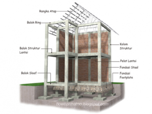
For this assignment, the housing structure follow the preceding design of house roofing structure. After recognizing and gathering information from search engine, additional length of beam is required to be cast inside concrete as a foundation shown in below figure.
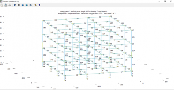
Therefore, correspond to the recommendation the utilized model is shown below. The structure has simple designing consist only with squared arrangement of beams from the ground level through the top. A more difficult arrangement could be done; however, lack of imagination prohibit the novel design. The dimension was made closed to the actual (1:1) house.In the software we could try download example of model from the website and manipulate the data as desired.
For this case we need to consider:
- Number of nodes
- Nodes location
- Number of beam element
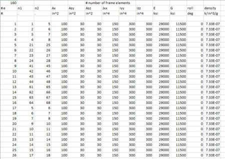
- The connectivity of each beam from nodes and properties
- Imposed load either centralized or uniform
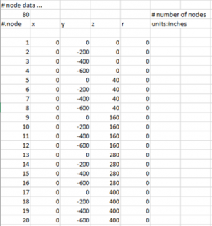
Set the nodes and location, determine by 3 dimensions composed with x y z axis, r as complement for round shapes structure are filled with 0 as the design doesn’t promote any round/circular shape. One should consider the applied unit to avoid any mistake, for this assignment inch and kips are used. Here, 80 nodes are required to establish the model needed.
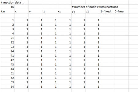
As nodes reaction depend on how the condition either we set free or fixed then, we should determine which nodes have to be set as it affects the calculation. Previously have stated that foundation is built as basis of the house, therefore 16 important nodes set fixed.
Then, we determine beam which connects specific node as the original mode has already stipulated. We could determine beam’s positions, properties such as elasticity, degree of roll, density, inertia and so on.
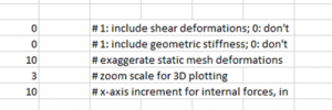
Because the simulation is undergoing simple static load, sear and geometric stiffness is not considered or negligible.
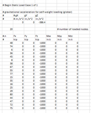
Figure above, show the load case given to the structure. Gravity plays role as mass act as internal load, as general measurement is 386.4 in/s2 acting downward then gZ should be filled as mentioned. External load can be either axial or moment force, for this simulation model is imposed only from z downward direction on several nodes in an extreme 1000 kip, therefore, tangible deformation can be seen. The imposed nodes are selected randomly using Ms. Excel function “randbetween(0,80)”.
Then the excel file can be saved after the code has finished as desired. Shown below the file saved as assignment6.csv, then we could open frame3dd.exe.
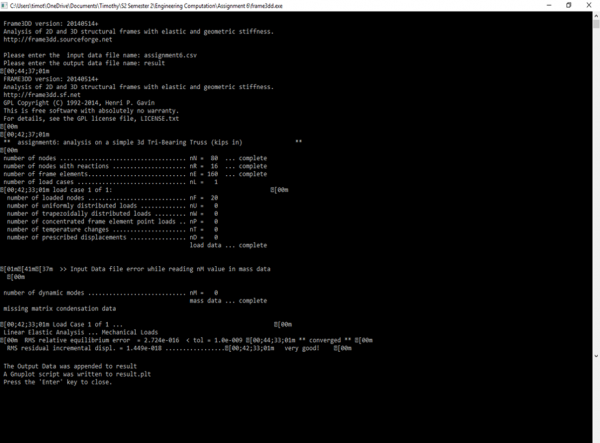
The interface shown below, statement asking us to enter the input data file should be filled with ‘assignment6.csv’ while the output data file is chosen ‘result’.
Shown above the processed after running the system. If no error or fail to be found, the system will finish the whole calculation.
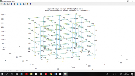
Then separated files are produced automatically, consisting result and output from the simulation filled with data which we can analyse.Above shown from Gnuplot file from the result. Yellow and green colours indicate the deformation and deflection occurrence, while the blue colour indicated the original beam condition before imposed 1000 kip downward from chosen nodes.
Data from the simulation can be seen from the attachment, further changes as it can be shown in graph will be conducted later.
From the simulation, it is known that frame 3DD is a powerful software to help engineers determine their model by imposing loads internally or externally, then show the behaviour of the model which could assist on the decision either reconstruction the model or give any retrofit to enhance the quality and characteristic of the model as verification and validation are conducted afterward. This is important because the engineer’s decision it to be held accountable for the safety and feasibility of the system.
