Muhammad Annawfal Rizky Sihotang
Introduction
Pagi Teknik ! I am Muhammad Annawfal Rizky Sihotang, a Mechanical Engineering student batch 2021. You can call me Kiki
Currently, taking numerical method class with Pak DAI.
NPM: 2106718281
Major: Mechanical Engineering
E-mail: annawfalrizky14@gmail.com
Numerical Method
Hydrogen Tank Design and Optimization Project
A pressurized hydrogen tank, also known as a hydrogen storage vessel or hydrogen cylinder, is a specialized container designed to store hydrogen gas under high pressure. It is constructed using materials that can withstand the forces exerted by the high-pressure hydrogen gas.These tanks are typically made of strong and lightweight materials such as carbon fiber-reinforced composites or high-strength steel alloys. The tank's design incorporates safety features to ensure the containment and integrity of the stored hydrogen.The pressurized hydrogen tank is an essential component in various applications, including hydrogen fuel cell vehicles, hydrogen refueling stations, industrial processes, and energy storage systems. It allows for the safe storage and transportation of hydrogen gas, enabling its use as a clean and efficient energy source.
Coding and Calculating
Initializing Surface Area for hydrogen tank
import numpy as np
from scipy.optimize import minimize
def objective(x):
# x[0] represents radius, x[1] represents height
radius = x[0]
height = x[1]
# Calculate the surface area of thte cylinder
surface_area = 2 * np.pi * radius * (radius + height)
return surface_area
def constraint(x):
# x[0] represents radius, x[1] represents height
radius = x[0]
height = x[1]
# Calculating the internal volume of the cylinder
volume = np.pi * radius**2 * height
# Difference between the volume and the desired value
return volume - 1000
# Initial value of radius and height
x0 = [5.0, 10.0]
# Variable constraints (radius and height)
bounds = [(0, None), (0, None)]
constraint_dict = {'type': 'eq', 'fun': constraint}
result = minimize(objective, x0, method='SLSQP', bounds=bounds, constraints=constraint_dict)
# Optimization results
print("Optimization results:")
print("Radius: {:.2f} cm".format(result.x[0]))
print("Height: {:.2f} cm".format(result.x[1]))
print("Surface Area: {:.2f} cm^2".format(result.fun))OUTPUT
Optimized results:
Radius: 6.5 cm
Height: 10.5 cm
Surface Area: 574.79 cm^2
Finding The Thickness of The Pressure Tank (8 bar)
r = 5.52e-2 # Tank Radius
p = 800000 # 8 Bar Pressure
t = 2.7e-3 # Minimum Thickness

while t < 11.05e-3:
  hoop = (p * r) / t
  print('Thickness', t, 'hoop stress =', hoop, "Pa")
  t += 1e-3
if hoop > 215e9: #Yield Strength of AISI 304
  break
OUTPUT
Thickness 0.010700000000000001 hoop stress = 4127102.8037383175 Pa
Cost Constraints
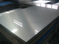
We conducted research on various distributor websites that offer Stainless Steel 304 plates ranging from 2-10 mm in thickness. After careful consideration, we found a supplier offering 5 mm thick plates at a cost of Rp.135,000 per plate. These plates have dimensions of 5 mm x 20 cm x 20 cm. Based on this information, we calculated that for a surface area of 574.79 cm^2, the cost of one unit would be approximately Rp.190,000.
This pricing structure allows us to stay within our budget constraint of Rp.500,000. Furthermore, since the cost of one unit falls within our budget, we can afford to purchase an additional unit with the same surface area as a backup. This decision aligns with our objective and ensures that we have an extra unit available.
Conclusions
Our project focuses on optimizing the design of pressurized hydrogen tanks using the compressed gas storage method. The objective is to achieve a balance between low cost and the use of high-quality, compatible materials. We prioritize cost-effectiveness without compromising safety or performance. Material compatibility is crucial to ensure efficient and secure hydrogen storage, avoiding any reactions or degradation that may lead to hazards. The design is aimed at maximizing storage capacity while minimizing weight and size, ensuring structural integrity and ease of manufacturing and installation. Safety features, environmental sustainability, operational efficiency, regulatory compliance, and lifecycle analysis are additional considerations that shape our approach. By carefully navigating these constraints and considerations, we strive to deliver an optimized solution that combines affordability, material compatibility, and a well-designed pressurized hydrogen tank.
Energy Conversion System
Class Summary [Monday, 30 October 2023]
Pak DAI shared Einstein's famous quote that proclaims that everyone possesses innate intelligence, or "genius," within them. However, this potential for brilliance is realized when we combine our efforts with a steadfast belief in ourselves and our ability to complete tasks to perfection.
In relation to the previous lecture on energy, we learned that energy is an essential and constant resource that cannot be created or destroyed. Instead, it serves as a vital force that plays a fundamental role in our daily lives, taking on various forms and functions. Energy can be converted or transformed from one form to another, for instance, from electrical energy to kinetic energy. This process of energy conversion, also known as energy transformation, is a pervasive occurrence that happens continually, throughout the day and in various contexts. There are numerous distinct types of energy, including thermal, electrical, nuclear, electromagnetic, mechanical, chemical, and sound energy, to name a few.
When we speak of "energy transformation," we are referring to the specific process of changing one form of energy into another. It's important to note that whether energy is transferred or transformed, the total quantity of energy remains constant, as dictated by the law of conservation of energy. This principle asserts that energy cannot be created or destroyed; it can only change its form, ensuring that the total energy in a closed system remains unchanged.
CFD Simulation [Wednesday, 1 November 2023]
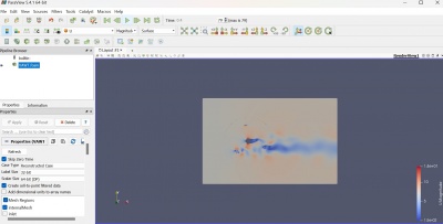
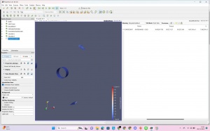
During our second session with Mr. DAI, we had the opportunity to visit the CFD Lab located on the third floor of the DTM Building. At the beginning of the class, we were introduced to the process of simulating a Vertical-Axis Wind Turbine (VAWT) using the CFDSOF and Paraview applications.
Before launching Paraview, we were instructed to first download the CFDSOF Application. Additionally, we were given access to the VAWT file via our WhatsApp Group, which we also needed to download. Once we had the VAWT file, the next step was to run the CFDSOF Application from the command prompt and follow the specific scripting instructions provided within the VAWT file.
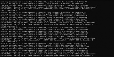
The outcome was determined with a wind velocity set at 7 m/s, whereas Bang Edo initially utilized 8 meters per second for the simulation. Following some calculations and a series of iterations in the command prompt, we arrived at a simulation time of approximately 0.4 seconds.
Calculating torque [Wednesday, 8 November 2023]
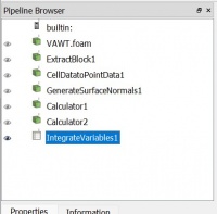
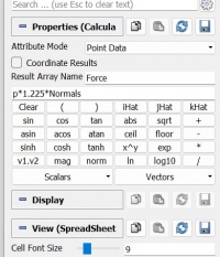
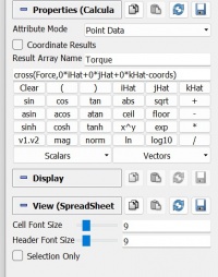
Following the completion of the CFD simulation, we proceed to calculate the torque using parameters discerned from the visual representation. Subsequently, we obtain results from the simulation.
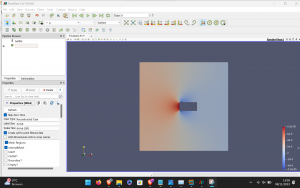
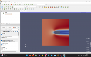
Velocity & Pressure Mesh Result
Static 2-Dimensional Simulation of a Single Blade
Known
Simulation mode: Steady-state, laminar, and incompressible
Initial condition = 0 m/s velocity
Geometry used in the simulation: 1 m X 3 m X 1 m
Base mesh: 10 m X 10 m X 0.1 m
Velocity reference value: 0.01 m/s
Simulation mode: Steady-state, laminar, and incompressible
Initial condition = 0 m/s velocity
The illustration displays an elevated pressure region situated at the leading edge of a blade, a phenomenon that plays a role in propelling the turbine. In theory, expanding the surface area of the blade leads to increased pressure; however, this augmentation also brings about a rise in weight due to the need for additional material.
Radial Gas Turbine Basic Principles
Explanation Video https://www.youtube.com/watch?v=f-1nfIenRAQ
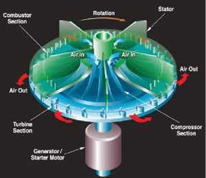
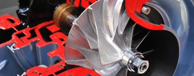
A radial gas turbine, also known as a radial flow turbine, is a type of gas turbine where the working fluid flows radially outward from the center of the turbine. This is in contrast to axial turbines, where the flow is parallel to the axis of rotation. Radial turbines are often used in various applications, including small-scale power generation, turbochargers, and some aerospace applications.
Key Principles:
- Centrifugal Compression: The impeller imparts centrifugal force to the incoming air, causing it to move radially outward and compress.
- Radial Flow Through Turbine: Unlike axial turbines where the flow is parallel to the axis, radial turbines have a radial flow, with the fluid moving outward from the center.
- Energy Conversion in Turbine: The expansion of high-pressure, high-temperature gas through the radial turbine blades converts thermal energy into mechanical energy.
- Power Extraction: The rotating turbine wheel extracts mechanical power from the fluid flow, which can be utilized for various applications.
- Exhaust: The remaining energy in the fluid is released in the exhaust, completing the thermodynamic cycle.
It's important to note that the design and efficiency of radial gas turbines depend on factors such as blade geometry, materials, and the specific requirements of the application. Additionally, the principles discussed here are in the context of a basic radial gas turbine; actual designs may vary based on specific engineering considerations and applications.
Advantages:
Compact Size: Radial turbines are often more compact than axial turbines, making them suitable for applications where space is limited. Simplicity: The design of radial turbines is often simpler compared to axial turbines. Adaptability to Variable Conditions: Radial turbines can be more adaptable to variable flow conditions, making them suitable for certain applications like automotive turbochargers.
Disadvantages:
Lower Efficiency: Radial turbines may have lower efficiency compared to axial turbines, especially in high-flow applications. Limited Flow Capacity: They may not handle as high a volume of air or gas as efficiently as axial turbines. Limited Use in High-Performance Applications: Radial turbines may not be as suitable for high-performance applications, such as high-speed aircraft propulsion.
Force Comparison Result of Manual Calculation and Simulation
Assumptions
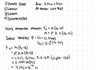
- Area of (0,14 x 0,5 )m
- Air density of 1,225 kg/m^3
- Steady-state, laminar, incompressible
Simulation
The Force Result from the simulation is -2.42312e-6 in the X-AXIS
Manual Calculation
(Note: The Answer is in Newton [N])
Force:
Analysis
- Fx(sim) = -2.42312e-6 N
- Fx(Calc) = 3.43e-6 N
The outcomes from both manual calculations and simulations showed significant differences, possibly due to human errors or inaccuracies during data input in the simulation software. Notably, the contrasting signs in calculated forces raised concerns. Negative signs in the simulation results differed from the positive values in manual calculations, likely stemming from different assumptions about how forces were calculated.
In manual calculations, the focus was on wind impacting the blade, analyzing how the force acted on the blade's surface. In contrast, the simulation approached it by considering the blade's influence on the wind, emphasizing the force exerted by the blade on the airflow.
These discrepancies in signs and magnitudes likely arose from these differing perspectives and assumptions. Mistakes in converting theoretical assumptions into simulation inputs may have contributed to the final result differences. To understand and reconcile these variations in computed forces, a thorough examination of both approaches and a comprehensive assessment of input parameters are necessary.

