Muhammad Annawfal Rizky Sihotang
Contents
[hide]- 1 Introduction
- 2 Numerical Method
- 3 Energy Conversion System
- 3.1 Class Summary [Monday, 30 October 2023]
- 3.2 CFD Simulation [Wednesday, 1 November 2023]
- 3.3 Calculating torque [Wednesday, 8 November 2023]
- 3.4 Velocity & Pressure Mesh Result
- 3.5 Radial Gas Turbine Basic Principles
- 3.6 Force Comparison Result of Manual Calculation and Simulation
- 3.7 Lab Visit [Wednesday, 27 November 2023]
- 3.8 Hydraulic and Pneumatic
- 3.9 Steam Turbine Report
Introduction
Pagi Teknik ! I am Muhammad Annawfal Rizky Sihotang, a Mechanical Engineering student batch 2021. You can call me Kiki
Currently, taking numerical method class with Pak DAI.
NPM: 2106718281
Major: Mechanical Engineering
E-mail: annawfalrizky14@gmail.com
Numerical Method
Hydrogen Tank Design and Optimization Project
A pressurized hydrogen tank, also known as a hydrogen storage vessel or hydrogen cylinder, is a specialized container designed to store hydrogen gas under high pressure. It is constructed using materials that can withstand the forces exerted by the high-pressure hydrogen gas.These tanks are typically made of strong and lightweight materials such as carbon fiber-reinforced composites or high-strength steel alloys. The tank's design incorporates safety features to ensure the containment and integrity of the stored hydrogen.The pressurized hydrogen tank is an essential component in various applications, including hydrogen fuel cell vehicles, hydrogen refueling stations, industrial processes, and energy storage systems. It allows for the safe storage and transportation of hydrogen gas, enabling its use as a clean and efficient energy source.
Coding and Calculating
Initializing Surface Area for hydrogen tank
import numpy as np
from scipy.optimize import minimize
def objective(x):
# x[0] represents radius, x[1] represents height
radius = x[0]
height = x[1]
# Calculate the surface area of thte cylinder
surface_area = 2 * np.pi * radius * (radius + height)
return surface_area
def constraint(x):
# x[0] represents radius, x[1] represents height
radius = x[0]
height = x[1]
# Calculating the internal volume of the cylinder
volume = np.pi * radius**2 * height
# Difference between the volume and the desired value
return volume - 1000
# Initial value of radius and height
x0 = [5.0, 10.0]
# Variable constraints (radius and height)
bounds = [(0, None), (0, None)]
constraint_dict = {'type': 'eq', 'fun': constraint}
result = minimize(objective, x0, method='SLSQP', bounds=bounds, constraints=constraint_dict)
# Optimization results
print("Optimization results:")
print("Radius: {:.2f} cm".format(result.x[0]))
print("Height: {:.2f} cm".format(result.x[1]))
print("Surface Area: {:.2f} cm^2".format(result.fun))OUTPUT
Optimized results:
Radius: 6.5 cm
Height: 10.5 cm
Surface Area: 574.79 cm^2
Finding The Thickness of The Pressure Tank (8 bar)
r = 5.52e-2 # Tank Radius
p = 800000 # 8 Bar Pressure
t = 2.7e-3 # Minimum Thickness

while t < 11.05e-3:
  hoop = (p * r) / t
  print('Thickness', t, 'hoop stress =', hoop, "Pa")
  t += 1e-3
if hoop > 215e9: #Yield Strength of AISI 304
  break
OUTPUT
Thickness 0.010700000000000001 hoop stress = 4127102.8037383175 Pa
Cost Constraints
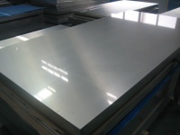
We conducted research on various distributor websites that offer Stainless Steel 304 plates ranging from 2-10 mm in thickness. After careful consideration, we found a supplier offering 5 mm thick plates at a cost of Rp.135,000 per plate. These plates have dimensions of 5 mm x 20 cm x 20 cm. Based on this information, we calculated that for a surface area of 574.79 cm^2, the cost of one unit would be approximately Rp.190,000.
This pricing structure allows us to stay within our budget constraint of Rp.500,000. Furthermore, since the cost of one unit falls within our budget, we can afford to purchase an additional unit with the same surface area as a backup. This decision aligns with our objective and ensures that we have an extra unit available.
Conclusions
Our project focuses on optimizing the design of pressurized hydrogen tanks using the compressed gas storage method. The objective is to achieve a balance between low cost and the use of high-quality, compatible materials. We prioritize cost-effectiveness without compromising safety or performance. Material compatibility is crucial to ensure efficient and secure hydrogen storage, avoiding any reactions or degradation that may lead to hazards. The design is aimed at maximizing storage capacity while minimizing weight and size, ensuring structural integrity and ease of manufacturing and installation. Safety features, environmental sustainability, operational efficiency, regulatory compliance, and lifecycle analysis are additional considerations that shape our approach. By carefully navigating these constraints and considerations, we strive to deliver an optimized solution that combines affordability, material compatibility, and a well-designed pressurized hydrogen tank.
Energy Conversion System
Class Summary [Monday, 30 October 2023]
Pak DAI shared Einstein's famous quote that proclaims that everyone possesses innate intelligence, or "genius," within them. However, this potential for brilliance is realized when we combine our efforts with a steadfast belief in ourselves and our ability to complete tasks to perfection.
In relation to the previous lecture on energy, we learned that energy is an essential and constant resource that cannot be created or destroyed. Instead, it serves as a vital force that plays a fundamental role in our daily lives, taking on various forms and functions. Energy can be converted or transformed from one form to another, for instance, from electrical energy to kinetic energy. This process of energy conversion, also known as energy transformation, is a pervasive occurrence that happens continually, throughout the day and in various contexts. There are numerous distinct types of energy, including thermal, electrical, nuclear, electromagnetic, mechanical, chemical, and sound energy, to name a few.
When we speak of "energy transformation," we are referring to the specific process of changing one form of energy into another. It's important to note that whether energy is transferred or transformed, the total quantity of energy remains constant, as dictated by the law of conservation of energy. This principle asserts that energy cannot be created or destroyed; it can only change its form, ensuring that the total energy in a closed system remains unchanged.
CFD Simulation [Wednesday, 1 November 2023]
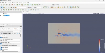
During our second session with Mr. DAI, we had the opportunity to visit the CFD Lab located on the third floor of the DTM Building. At the beginning of the class, we were introduced to the process of simulating a Vertical-Axis Wind Turbine (VAWT) using the CFDSOF and Paraview applications.
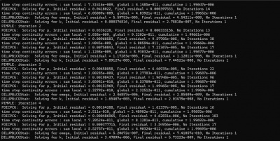
Before launching Paraview, we were instructed to first download the CFDSOF Application. Additionally, we were given access to the VAWT file via our WhatsApp Group, which we also needed to download. Once we had the VAWT file, the next step was to run the CFDSOF Application from the command prompt and follow the specific scripting instructions provided within the VAWT file.
The outcome was determined with a wind velocity set at 7 m/s, whereas Bang Edo initially utilized 8 meters per second for the simulation. Following some calculations and a series of iterations in the command prompt, we arrived at a simulation time of approximately 0.4 seconds.
Calculating torque [Wednesday, 8 November 2023]
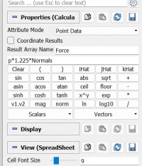
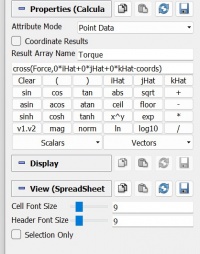
Following the completion of the CFD simulation, we proceed to calculate the torque using parameters discerned from the visual representation. Subsequently, we obtain results from the simulation.
Velocity & Pressure Mesh Result
Static 2-Dimensional Simulation of a Single Blade
Known
Simulation mode: Steady-state, laminar, and incompressible
Initial condition = 0 m/s velocity
Geometry used in the simulation: 1 m X 3 m X 1 m
Base mesh: 10 m X 10 m X 0.1 m
Velocity reference value: 0.01 m/s
Simulation mode: Steady-state, laminar, and incompressible
Initial condition = 0 m/s velocity
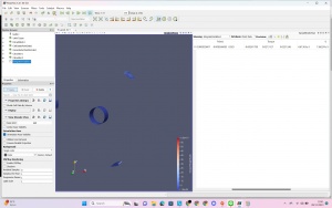
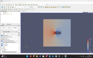
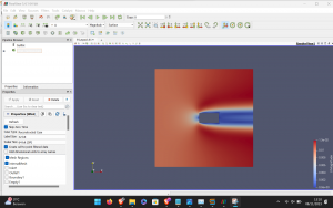
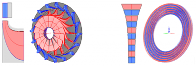
The illustration displays an elevated pressure region situated at the leading edge of a blade, a phenomenon that plays a role in propelling the turbine. In theory, expanding the surface area of the blade leads to increased pressure; however, this augmentation also brings about a rise in weight due to the need for additional material.
Radial Gas Turbine Basic Principles
Explanation Video https://www.youtube.com/watch?v=f-1nfIenRAQ
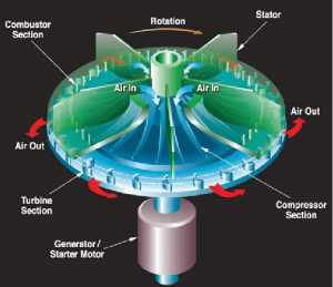
A radial gas turbine, also known as a radial flow turbine, is a type of gas turbine where the working fluid flows radially outward from the center of the turbine. This is in contrast to axial turbines, where the flow is parallel to the axis of rotation. Radial turbines are often used in various applications, including small-scale power generation, turbochargers, and some aerospace applications.
Key Principles:
- Centrifugal Compression: The impeller imparts centrifugal force to the incoming air, causing it to move radially outward and compress.
- Radial Flow Through Turbine: Unlike axial turbines where the flow is parallel to the axis, radial turbines have a radial flow, with the fluid moving outward from the center.
- Energy Conversion in Turbine: The expansion of high-pressure, high-temperature gas through the radial turbine blades converts thermal energy into mechanical energy.
- Power Extraction: The rotating turbine wheel extracts mechanical power from the fluid flow, which can be utilized for various applications.
- Exhaust: The remaining energy in the fluid is released in the exhaust, completing the thermodynamic cycle.
It's important to note that the design and efficiency of radial gas turbines depend on factors such as blade geometry, materials, and the specific requirements of the application. Additionally, the principles discussed here are in the context of a basic radial gas turbine; actual designs may vary based on specific engineering considerations and applications.
Advantages:
Compact Size: Radial turbines are often more compact than axial turbines, making them suitable for applications where space is limited. Simplicity: The design of radial turbines is often simpler compared to axial turbines. Adaptability to Variable Conditions: Radial turbines can be more adaptable to variable flow conditions, making them suitable for certain applications like automotive turbochargers.
Disadvantages:
Lower Efficiency: Radial turbines may have lower efficiency compared to axial turbines, especially in high-flow applications. Limited Flow Capacity: They may not handle as high a volume of air or gas as efficiently as axial turbines. Limited Use in High-Performance Applications: Radial turbines may not be as suitable for high-performance applications, such as high-speed aircraft propulsion.
Force Comparison Result of Manual Calculation and Simulation
Assumptions
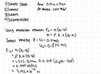
- Area of (0,14 x 0,5 )m
- Air density of 1,225 kg/m^3
- Steady-state, laminar, incompressible
Simulation
The Force Result from the simulation is -2.42312e-6 in the X-AXIS
Manual Calculation
(Note: The Answer is in Newton [N])
Force:
Analysis
- Fx(sim) = -2.42312e-6 N
- Fx(Calc) = 3.43e-6 N
The manual calculations and simulations we conducted showed some significant differences. These variations could be due to mistakes made by humans or inaccuracies in the data input into the simulation software. One noticeable issue was the conflicting signs in the calculated forces. The simulation results had negative values, while the manual calculations had positive values. This difference likely came from different ways of thinking about how forces are calculated.
In the manual calculations, we focused on how the wind affects the blade, looking at how the force acts on the blade's surface. On the other hand, the simulation looked at it from the perspective of how the blade influences the wind, emphasizing the force exerted by the blade on the airflow.
These differences in signs and magnitudes probably came from these distinct perspectives and assumptions. Errors in translating theoretical assumptions into inputs for the simulation might have played a role in the variations we observed. To make sense of and resolve these differences in calculated forces, we need to carefully examine both approaches and thoroughly assess the input parameters used in the simulations.
My Conscious Effort
Conscious effort in the design and operation of radial gas turbines represents a pivotal aspect of optimizing performance and efficiency in aerospace and industrial applications. Engineers and operators engage in a meticulous process, considering factors such as blade geometry, aerodynamics, and thermodynamics to enhance the turbine's overall efficiency. Radial gas turbines, characterized by their unique blade arrangement, require a keen understanding of the complex fluid dynamics involved in the gas flow through the turbine stages. The conscious effort is directed towards minimizing energy losses, maximizing power output, and ensuring the durability of turbine components under high-temperature and high-pressure conditions. Moreover, ongoing advancements in materials science contribute to the conscious effort by enabling the development of innovative alloys and coatings that enhance the turbine's resistance to corrosion and wear. In essence, the conscientious approach to radial gas turbine design and operation is essential for achieving optimal performance, reliability, and sustainability in the evolving landscape of power generation and aviation technologies.
Lab Visit [Wednesday, 27 November 2023]
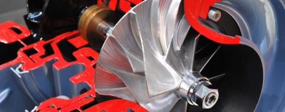
During our visit to the CCIT lab in Kukusan, Depok on November 27, 2023, we had the opportunity to explore various works and projects undertaken by Mr. DAI and his colleagues. Among the intriguing exhibits, one that particularly fascinated me was an in-depth presentation on the intricate mechanisms of a turbocharger. Witnessing the tangible manifestation of this technology was a captivating experience.
How does turbochargers work?
Turbochargers operate by harnessing exhaust gas energy from an internal combustion engine to compress incoming air before it enters the engine's cylinders. Consisting of a pair of fans, the turbine and the compressor, connected by a common shaft, the turbocharger is mounted on the engine. As exhaust gases flow over the turbine blades, they cause the turbine to spin. This rotation, in turn, drives the connected compressor, which draws in and compresses fresh air before delivering it to the engine's intake manifold. The compressed air allows for a greater volume of oxygen to mix with fuel, resulting in improved combustion efficiency and increased engine power. This forced induction system enhances overall engine performance and efficiency, particularly at higher altitudes or under heavy load conditions.
Hydraulic and Pneumatic
Hydraulic and pneumatic systems are both forms of fluid power systems that utilize the properties of liquids and gases, respectively, to transmit force and energy. Here's a brief explanation of how each system works:
Hydraulic Systems: In a hydraulic system, the working fluid is typically a liquid, commonly hydraulic oil. The system consists of a hydraulic pump, which pressurizes the fluid, and a network of pipes or tubes to transmit the pressurized fluid to various hydraulic motors or actuators. These actuators, such as cylinders or hydraulic motors, convert the hydraulic energy back into mechanical work. The basic principle is Pascal's law, which states that any change in pressure applied to an enclosed fluid is transmitted undiminished to all portions of the fluid and to the walls of its container. By controlling the flow of hydraulic fluid and adjusting pressure, hydraulic systems can generate powerful and precise linear or rotary motion.
Pneumatic Systems: In pneumatic systems, the working fluid is air. A pneumatic system typically includes a compressor, which compresses air and stores it in a receiver tank. The compressed air is then directed through a network of pipes to pneumatic actuators, such as cylinders. When the compressed air is released into these actuators, it expands, generating mechanical motion. Pneumatic systems are widely used in various applications due to their simplicity, cleanliness, and cost-effectiveness. They are often employed in tasks that require rapid and repetitive motion, and their components are generally lightweight.
In both hydraulic and pneumatic systems, valves are crucial components that control the flow and pressure of the fluid or air, allowing for precise and controlled movement of the actuators. The choice between hydraulic and pneumatic systems depends on the specific application requirements, such as the amount of force needed, the desired speed of operation, and environmental factors.
Steam Turbine Report
Preface
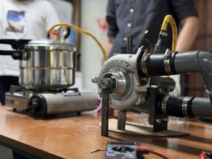
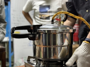
On December 20th, an air of anticipation filled the laboratory as our team embarked on a groundbreaking experiment involving steam turbines. The objective of the day was to explore the potential enhancements and efficiencies brought about by the integration of turbochargers with steam technology. As the team of engineers and scientists meticulously set up the experimental apparatus, the room buzzed with a palpable blend of curiosity and determination. The steam turbine, a symbol of industrial prowess, stood at the center of attention, ready to undergo a transformative journey into uncharted territory.
With safety protocols in place, the experiment commenced, and the rhythmic hum of machinery reverberated throughout the laboratory. As turbochargers were engaged, a captivating dance of energy unfolded, capturing the attention of everyone present. Real-time data streaming and careful monitoring revealed the intricate dynamics between steam and turbochargers. The experiment wasn't just a scientific endeavor; it was a voyage into the synergy between traditional steam technology and the cutting-edge integration of turbocharged systems. The promising results sparked discussions among the team, paving the way for further exploration and refinement in our ongoing quest for more sustainable and efficient energy solutions. The day culminated in a sense of achievement, marking December 20th as a pivotal moment in our journey toward innovative steam-driven technology.
The integration of turbochargers showcased their adaptability and efficiency in enhancing the overall performance of steam turbines. By harnessing the exhaust energy from the steam turbine, the turbochargers facilitated a dynamic interplay of forces, contributing to increased power output and improved energy efficiency.
One of the key functions of the turbochargers was evident in their ability to optimize the utilization of steam energy, effectively enhancing the power generation process. The experiment highlighted how these turbocharged systems could potentially revolutionize traditional steam technology, offering a promising avenue for more sustainable and efficient energy solutions.
Working Principle
The functioning of a steam turbine relies on the dynamic interaction of steam. Steam, propelled at high velocity through nozzles, impacts rotating blades attached to a disc on a shaft. This swift steam generates dynamic pressure on the blades, initiating simultaneous rotation of both the blades and the shaft. Essentially, the steam turbine operates by extracting the pressure energy from the steam and transforming it into kinetic energy as the steam flows through the nozzles.
The conversion of kinetic energy then performs mechanical work on the rotor blades. The rotor, linked to a steam turbine generator, serves as an intermediary. The turbine generator gathers mechanical energy from the rotor and converts it into electrical energy. Due to the straightforward construction of steam turbines, their vibration is considerably lower compared to other engines operating at the same rotational speed. Various types of governing systems are employed to enhance the control of turbine speed.
Experiment Calculation
When energy is injected into the system, the associated value will be positive. Conversely, if the energy exits the system, the corresponding value will also be positive.
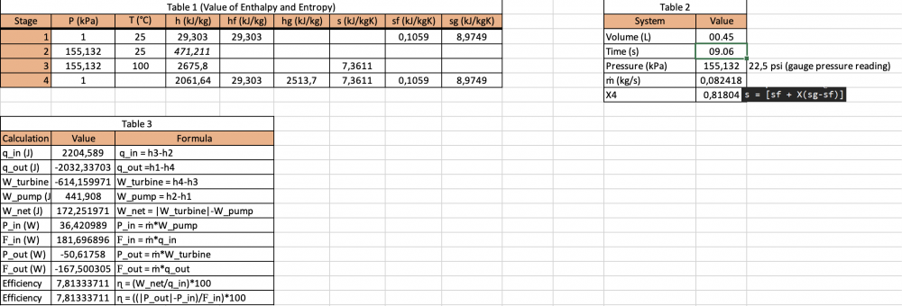
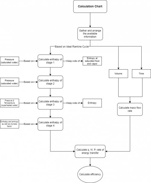
To simplify the calculation of the system's efficiency, a spreadsheet is created. Generally, this spreadsheet consists of three main tables, arranged based on the significance of the variables and parameters at hand.
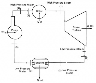
The provided flowchart outlines the steps for determining the system's efficiency.
Volume = 450 ml Time = 9.6 S
Conclusion
From the calculation we get the results about :
Pin : 36,42 W
Pout : -50,61 W
Efficiency : 7,81%
Self Assesment (Munasabah)
Throughout the Energy Conversion System classes, I consistently endeavored to give my best in terms of learning, studying, and comprehending the course materials. However, I am cognizant that there were instances when my efforts might not have been optimal. Recognizing this, I am committed to elevating the quality of my commitment and exertion.
Moreover, beyond the specific instances mentioned earlier, there is a recognition that there exists a continuous opportunity for enhancement in the levels of effort and critical thinking. Striving for excellence is an ongoing journey, and I am dedicated to making strides toward creating a more promising future for myself.
Delving into the concept of conscious thinking has underscored the significance of intention. It has become apparent to me that intention serves as a guiding force, providing clarity amidst uncertainties. Without a clear intention, we may find ourselves adrift, unsure of our actions and decisions. Therefore, I am placing greater emphasis on aligning my intentions with my actions, recognizing that this conscious approach is pivotal for personal and academic growth.
Video Report
https://www.youtube.com/watch?v=T59fim1QevQ
This is a video containing my explanation about the steam turbine report, I hope this video can make a better understanding about my reflection and how i flow through a journey in energy conversion system class

