Harry Swaramadani
Contents
Biodata
Name: Harry Swaramadani NPM: 1806227963
Place and date of birth: Jakarta, 3rd June 2000
Hobby: Swimming
I am a student in the University of Indonesia majoring in Mechanical engineering. This is my 6th semester.I'm looking forward to learn about Energy Conversion. I am currently carrying out the on the job training at PT MRT Jakarta. It turns out that there are many events surrounding energy conversion when I did a field survey to review the work system of the screen door platform and also the energy cycle of the cooling system from the chiller and cooing tower.
Pertemuan (23/02/2021)
my name is harry swaramadani and I am mechanical engineering student. Currently in 6 semester. basically I have an interest in mechanical engineering because it is a versatile subject. we can apply it anywhere in life because basically all systems in this world need machines. Now we can move to our topics that discussing about energy conversion.
energy conversion learning begins with discussing justice for all mankind. But before that, it turned out that there were a lot of energy conversion processes around us, for example in my internship program at PT MRT Jakarta. there are many process in my surrounding that applied energy conversion. For the illustration when I did a field survey to review the work system of the screen door platform and also the energy cycle of the cooling system from the chiller and cooing tower.The conversion or energy change that occurs here is wind energy into water energy for the cooling tower and also electrical energy to kinetic energy for the screen door
Now we can observe what the justice mean .basically being fair to every creature of the law is mandatory. The justice here means in behaving to everyone, we consider them all the same or equal, no one is considered lower or higher. So that the treatment we give to the environment around us can be well received and avoid social inequality.
In this case we as mechanical engineering must be able and associate justice through the realm that we live in. Through the application of several disciplines such as reaction action and fluid mechanics, we know how this energy flow moves and has a profound impact on the environment it is in. This indicates there is an energy balance in the process.
In addition, talking about energy that we can apply to elementary school children through the mechanical engineering approach is that energy itself is the ability to do work. ItIt can be seen but cannot be felt The way we do work is by force / force so that the work is resolved. But here, when we do work on something there will definitely be a reciprocal response to our style. Like Newton's Law number 3, namely F1 = F2 or what we are more familiar with the concept of action = reaction. This is closely related to the principle of justice itself, such as what we do to someone, whether bad or good, then we will also get the same response so that no party is harmed. Talking about technology, actually technology itself can be applied with justice. for example, we design technology to be able to help humans in need. like making technology simple but has the same benefits as more expensive and complex tools. for example, such as the use of an incubator with a bulb illuminated in remote or primitif villages
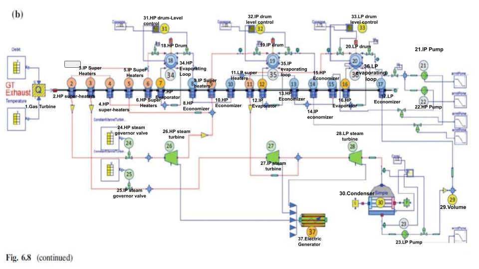
basically i haven't learned more yet, i just translate the component of this schematic diagram. and in essence this combined cycle with 3 staged is to produce the electrical energy with several cycles to achieve an efficient system and it all stard from the gas turbine.
Pertemuan (24/02/2021)
This is the Scgematic Diagram of the Combined Cycle
At the previous meeting we discussed the interests of each student that can be applied in mechanical engineering. In this case, the discussion of energy conversion begins by discussing justice based on engineering science. Many of us have different meanings in interpreting the meaning of justice itself, but basically fair or justice in here is having the same attitude towards everyone and not differentiating from one another or better known as being equal. This explanation of course can be understood also for elementary school students. The principle of fairness here must also correlate with engineering science, which is basically technology made to uphold justice in order to help human needs and jobs. In addition, we are also asked to translate a schematic diagram depicting a multistage system in a combine cycle turbine. The translation here is adjusted to each part in the cycle. However, for the working system itself, we do not yet understand more about the function of each of its components. Broadly speaking, this system has 3 stages that function to streamline the energy released and see how much electricity is generated in the system.
Homework (28/02/2021)
Pada tugas untuk pertemuan berikutnya, saya diminta untuk memahami apa itu software OpenModelica beserta peruntukannya. OpenModelica sendiri adalah lingkungan sumber terbuka yang gratis berdasarkan bahasa pemodelan Modelica untuk pemodelan, simulasi, pengoptimalan, dan analisis sistem dinamis yang kompleks. Perangkat lunak atau software ini secara aktif dikembangkan oleh Open Source Modelica Consortium yaitu sebuah organisasi non-pemerintah nonprofit.
Tujuan dari open modelica sendiri adalah untuk menciptakan lingkungan pemodelan, kompilasi dan simulasi open source modelica yang komprehensif berdasarkan perangkat lunak yang dapat mendistribusikan model dalam bentuk biner dan kode sumber untuk penelitian, pengajaran dan penggunaan di dunia industri.
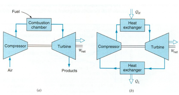
dalam praktik ini saya membuat pemodelan thermosysro dari brayton cycle 1 stage untuk pengujian cycle dari gas turbine engines. Pada dasarnya cycle ini terbagi menjadi dua yakni open cycle maupun closed cycle gas turbine engine. Perbedaannya disini adalah pada open cycle terdapat combustion chamber untuk gambar (a) sedangkan closed cycle terdapat Heat exchanger untuk gambar (b).
Memang pada saat ini, siklus brayton hanya digunakan untuk turbin gas yang mana proses kompresi dan ekspansi berlangsung dalam mesin yang berputar. Secara Garis besar, Proses yang disebut Siklus Brayton ini, dapat diringkas menjadi 4 proses yang dapat dibalik secara internal seperti gambar berikut:
1-2 kompresi isentropik (dalam kompresor)
2-3 Penambahan panas dengan tekanan konstan
3-4 Ekspansi isentropik (dalam turbin)
4-1 Penolakan panas tekanan konstan
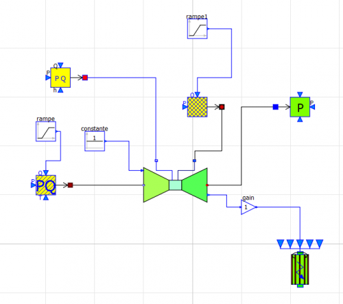
Seyelah memahami siklus bryton tersebut. Kita dapat menginterpretasikannya ke dalam sebuah software Open Modelica. Disini kita mencoba untuk membuat skema diagram yang lebih sederhana dari pertemuan sebelumnya, yakni skema single state dari open cycle gas turbine. Dalam proses pembuatan, kita dapat mencontoh skema dari ThermoSyspro yang bisa kita dapatkan dari System Libraries. Dari contoh tersebut, kita dapat melihat komponen apa saja yang dapat digukanan dalam pembuatan skema dengan cara melihat Path dari komponen tersebut lalu menggunakannya untuk membentuk skema baru dari single stage Open Cycle Gas Turbine.
kita lihat skema dari sistem tersebut pada gambar dibawah ini. komponen yang digunakan adalah rampe, rampe1, SourcePQ, SourcePQ1, fuelSourcePQ, gasTurbine, Constante, SinkP, gain dan generator. Dari skema tersebut, kita mengetahui bahwa terdapat 4 input. Input ini dibagi menjadi 2 yang berasal dari massa aliran dan juga humidity pada inlet gas serta yang berasal dari jenis bahan bakar dan juga massa aliran pada oxidizer. Setelah di proses dalam gas turbine selanjutnya sistem ini memiliki 2 tempat pengeluaran gas/energi sisa hasil pemakaian yang terdapat pada exhaust untuk mengeluarkan gas buang sisa keluar turbine karena pada open cycle tidak membutuhkan lagi gas tersebut untuk di sirkulasi. Selain itu terdapat generator untuk mengetahui seberapa besar tenaga listrik yang dihasilkan sistem pada saat keluar.
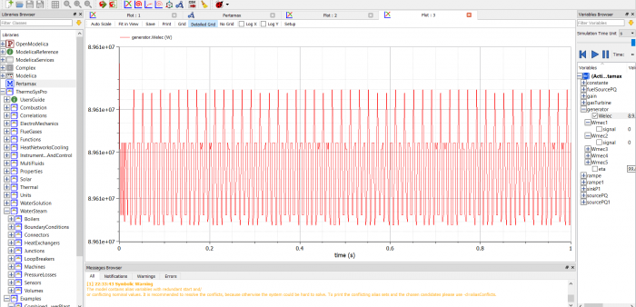
Setalah berhasil membuat skema tersebut, kita dapat mengatur parameter pada setiap komponen untuk mendapatkan hasil perhitungan seusai yang diharapkan. Pengaturan parameter disini berdasarkan angka yang telah tertera pada setiap part yang tertera di contoh combinecycled 3 stage sebelumnya. Setelah mengatur parameter, kita dapat melakukan running simulate untuk melihat grafik yang dihasilkan dalam sistem dari open cycle gas turbine ini dengan memilih welec pada bagian generator setelah mengklik tanda panah hijau kesamping di toolbar. berikut adalah bentuk grafiknya :
Pertemuan (02/03/2021)
Pada pertemuan hari ini dimulai dengan pembahasan apa itu yang dimaksud dengan system. Sistem sendiri dapat diartikan dengan perangkat atau unsur yang membentuk sebuah satu kesatuan yang saling berkoordinasi dan memiliki kesinambungan satu sama lain untuk dapat menjalankan sesuatu dengan baik sesuai arahan. Pada dasarnya contoh sistem ini terdapat dimana saja dalam ekhidupan sehari-hari, sebagai contoh yang paling dekat adalah sistem pencernaan yang tedapat pada diri kita. Hal tersebut merupakan proses mengkonsumsi makanan lalu diolah oleh tubuh kita untuk kebutuhan sehari-hari hingga proses pembuangan sisa makanan.
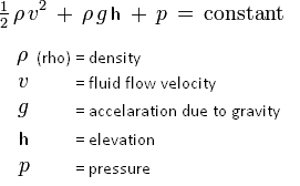
Dengan melihat berbagai sistem yang ada pastilah terjadi perubahan energi dalam sistem tersebut atau yang lebih kita kenal dengan konservasi energi. pada dasarnya konversi energi ini adalah proses perubahan energi dari bentuk semula ke dalam bentuk yang lain. Hal ini berguna untuk mengurangi penggunaan energi dalam sebuah sistem sehingga tercipta proses yang lebih efisien. Dari persamaan bernoulli, kita dapat melihat sebuah contoh dari konversi energi untuk mengurangi tekanan fluida dengan menaikkan kecepatan fluida. Dalam aliran yang berkecepatan kecepatan tinggi ini, melalui penyempitan, energi kinetik harus meningkat dengan mengorbankan energi tekanan. Maka dari itu tekanan adalah hal yang sangat vital dalam persamaan ini. Tekanan sendiri dapat diartikan dengan gaya per satuan luas dan juga Energi per satuan volume.
Berikut ini adalah persamaan bernoulli :
Working Principle Gas Turbine (04/03/2021)
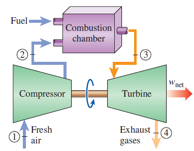
On this day, we have learned about the Gas Turbine Flow Chart Process. The process itself starts from Fresh air at ambient conditions is drawn into the compressor, Then the temperature and the pressure are raised due to the compressing air from compressor. In this case the temperature and the pressure are directly proportional. The high-pressure air from compressor proceeds into the combustion chamber with the fuel, where the fuel is burned at constant pressure. The resulting high temperature/hot gases as the output then enter the turbine to move it, where they expand to the atmospheric pressure while producing power. The exhaust gases leaving the turbine are thrown out (not recirculated), causing the cycle to be classified as an open cycle. Different from the previous process, for the closed cycle the combustion process is repalced by constant pressure heat addition process from an external source, and the exhaust process is replaced by a constant pressure heat rejection process to get the ambient air. It means that the output energy from the moving turbine will be used to move the compressor and move the generator to produce electricity. So, this called the bryton Cycle.
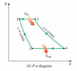
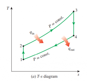
These are the T-S and P-V diagrams of an ideal Brayton cycle.This cycle is a steady flow process. The energy balance for a steady flow process can be expressed on a unit mass basis with neglecting the changed of kinetic and potential energies. The equation can be shown as :
(q in - q out) + (w in - w out) = h exit - h inlet
Therefore, heat transfers to and from the working fluid are
q in = h3 − h2 = cp(T3 − T2) and q out = h4 − h1 = cp(T4 − T1)
This equation is based on four internally reversible process that picturized from T-S diagram including :
1-2 Isentropic compression (in a compressor)
In this process, The temperature increase due to the gas compression, beside that there is a decreasing in gas volume. This represent the effects of an ideal adiabatic compressor
2-3 Constant-pressure heat addition
The unit gas mass is heated at constant pressure by the exchange of heat input. This is an isobaric process that represents of heat addition caused by the combustion of injected fuel. in this step, the graph reach the highest temperature.
3-4 Isentropic expansion (in a turbine)
The unit gass mass is isentropically expanded that indicates lower preesure and temperature but increasing in volume due to the expansion process.
4-1 Constant-pressure heat rejection
the bryton cycle is completed that The temperature is decreasing and also the volume of the unit gass mass due to heat rejection
From that cycle process, it stated that the 1-2 and 3-4 process are the isentropic that having an equal entropy, and also P2 = P3 and P4 = P1. it derived to the equation that,
T2/T1 = (P2/P1)^(k-1)/k = (P3/P4)^(k-1)/k = T3/T4
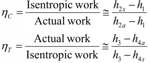
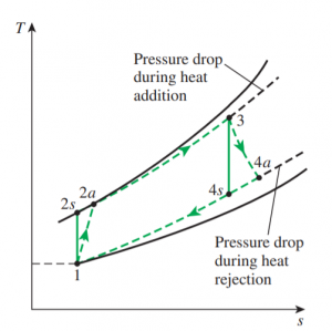
From that process, some pressure drop during the heat addition and heat rejection process is inevitable. There is a different between the actual work from turbine and compressore that indicates less work of turbine than the compressor due to the irreversibilities output. With the Isentropic efficiencies of the turbine and compressor, the deviation of actual compressor and turbine behaviour can be accounted by this equation :
This is the graph of the deviation of an actual gas -turbine cycle from the ideal Brayton Cycle as a result of irreversibilities :
Pertemuan (09/03/2021)
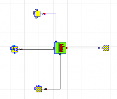
Today, we have learned about how to use the Open Modelica to make a simple design of the internal combustion scheme. It was started from the explanation of the list part that must be used. Basically it contains the input system, combustion chamber and also the output system which are denoted by the SourcePQ2, SourceFumee, and FuelSourcePQ1 as the part of input system, The GTCombustionChamber1 as the part of the Internal combustion and also the Sink1 as the part of the output system/ sink output. This design was made for internal combustion
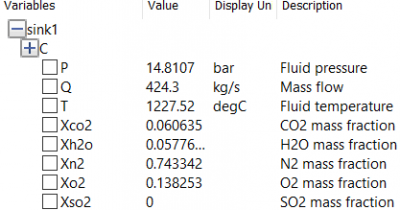
We input the several parameter to each part to set a goal of the simulation. We get the result in the form of numerical data that describes the fluid pressure, mass flow, temperature and also any gas content that contained at the output of the system. These are the results :
