Analisis aliran didalam Cyclone Separator dengan Simulasi CFD menggunakan CFDSOF
Analisis aliran didalam Cyclone Separator dengan Simulasi CFD menggunakan CFDSOF Abstrak
Contents
Pengantar
Abi Rizky
Cyclone separators or simply, cyclones, are separation devices which use the principles of inertia to remove particulate matter from flue gases. These are used in many air pollution control systems due to their ability to remove large particulate matters (PMs). And as such, protects finer filtration systems from having to filter larger, more abrasive particles, since finer filters tend to be more sensitive and are generally more expensive.
These devices work much like a centrifuge, but unlike a centrifuge, the flow of dirty air is continuous. The dirty gas is fed into the main chamber, which led the flow to form a vortex due to the geometry of the device. As the flow gets closer to the lower parts, the vorticity increases; however due to inertia, PMs cannot keep up with the vortex within the separator. This led to them being left behind and drop down through the outlet underneath the device. The flue gas then flows upwards, creating a new vortex as it reaches the gas outlet at the top due to buoyant forces.
Agus Nuryadi
The first systematic design based on the residence time theory for all groups of cyclones and hydrocyclones were proposed by Massarani (1997). In this principle, if the time it stays inside the cyclone is equal to or longer than the time required to hit the wall, a particle of a given size will be captured. The cut's size corresponds to the particle size that, if entered precisely at the center of the inlet pipe, enters the wall during the residence period (t) (Svarovsky, 1984). Massarani equation-related diameter of cut size (d50); parameter (K) Depending on the shape of the cyclone; the physical properties of the system; and the volumetric feed flow rate (Q), as revealed in the equation below.
Where g(cv) introduces the effect of concentration on the cut size diameter, g (cv) is approximately equal to one for studies with a heavily diluted suspension. Furthermore, The nomographs by Zanker can be used to make a preliminary estimate of the size of cyclone needed. The specialist manufacturers of hydrocyclone equipment should be consulted to determine the best arrangements and design for a particular application. Zanker’s method is outlined below and illustrated in the Example below and based on an empirical equation by Bradley (1960):
Where, d50 is the particle diameter for which the cyclone is 50 per cent efficient, Dc is diameter of the cyclone chamber, u is liquid viscosity, L is feed flow rate, pl = density of the liquid, and ps = density of the solid. The Euler number is the other significant parameter in the cyclone analysis (Eu). The pressure drop in the cyclone ( ∆ P) with the kinetic energy per unit volume of feeding refers to this dimensionless amount. Also, The greater the number of Euler values, the greater the equipment's cost of energy. By equation, the Euler number is defined.
where uc is the average velocity of the fluid in the cylindrical section of the cyclone. Parameter K and the Euler number (Eu) for the Lapple cyclone, as well as the range of gas velocity in the feed section (u), according to Massarani. The ratio between the mass of particles accumulated in the underflow and the mass of particles fed into the cyclone determined the overall efficiency of the separation (η).
Individual separation efficiency (η) is a parameter related to the equipment's separation efficiency for just one particle size. This variable is determined based on knowledge of the overall separation efficiency (η (head)) and the particles' grade distribution in the underflow and feeding, as shown in the following equation. An individual efficiency of separation of 50%, the cut size diameter.
The Eulerian-Lagrangian method and the multiphase particle in cell (MPPIC) method have been used in this study. The model of the MPPIC is a Model Collision in CFDSOF. First of all, PIC models are derived from a Liouville equation describing the time evolution of a particle distribution function.
Objektif
1. Performing CFD analysis on Cyclone Separator using various parameters obtained from literatures
2. Analyzing the result obtained from the CFD analysis, such as bulk diameter of the discrete phase, velocity fields, and pressure gradients.
3. Understanding the impacts of various boundary conditions on various aspects of the simulations, such as convergencies, how boundary conditions impact results, and how the flow itself behaves during simulation.
4. Applying knowledge regarding CFD analysis, such as how to choose timesteps for transient flows, making sure that the meshes are applied correctly, and applying boundary and flow conditions.
5. Verifying the results through the means of grid independence study, which ensures the calculations are correct regardless of the meshing, and the difference between results are within the margin of error.
6. Validating the results by comparing the results with literatures and real applications.
Metodologi
Model Komputasi dan Simulasi (EDO)
Simulation Boundary Condition
One of the most important aspect in preparing the simulation model is boundary condition. The boundary condition should be determined properly in the pre-processing stage of the simulation. The boundary condition should be set up as it can represent the actual condition of the case. In this case, the flow consist of flue gas and catalyst particle. Thus, The flow would be modeled as multiphase flow and multiphase Eularian-Lagrangian model would be used for this simulation. Therefore, they would be an additional boundary condition for the particle phase. The simulation would also be considered as turbulent flow. Reynold Average Navier Stokes (RANS) with SST k-ω model would be used in this simulation. The domain simulation consist of 3 boundary area: Wall, inlet, upper outlet, lower outlet. The lower outlet as shown in Fig. below.
The inlet boundary is set as velocity inlet, so that the inlet velocity of the flue gas,which is the primary fluid, is set up. The pressure at the inlet section will be calculated according to the inlet velocity and the outlet pressure. Both upper and lower boundary condition is set as outflow with the total zero of the total pressure. The zero total pressure does not actually represent the vacuum condition, but it is set such that would give a better way of getting how much the pressure difference or pressure drop occurs. In other word, instead of set up the specific value of the pressure at the outlet boundary condition, the solver would calculate how much the pressure drop occurs with the given velocity inlet. The wall boundary condition is set as no-slip condition. Hence, the velocity at the wall would be zero.
Hasil dan Pembahasan
Verifikasi
Validasi
Validasi Tekanan (Bintang)
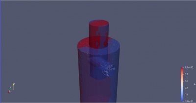
Based on ideal condition, pressure distribution should vary linearly by altitude, in which in this case variation by altitude is not significant due to only small change of altitude is present inside this small cyclone. The change on static pressure is more affected by the change in flow velocity. However, the reduction of static pressure is also quite small to give variation on the static pressure itself. Significant pressure gradient can only be observed near the outlet of the inflow, where the inlet flow hit the cyclone wall for the first time. At this location, the flow decelerates to zero, hence producing stagnation pressure, before being redirected due to the change in momentum caused by the cyclone wall itself and producing a vortex flow. In correct CFD simulation, this should always be the case with exception if the fluid velocity going near the speed of sound in which compressibility effect cannot be neglected which is not the case on this simulation. However, one of our simulation shows a different pressure distribution which was not in accordance to the ideal condition as shown in figure (number).
The pressure distribution in this case was really high on one side and really low on the other side, and both having insignificant pressure change vertically. This abrupt change in pressure on each side of the cyclone is not in accordance to the ideal condition, as it should be as explained previously. One parameters that shows the error of this simulation is the value of the pressure that reaches 1e36 Pascal. After a long discussion, we found that the reason why this simulation isn't correct is because the convergence, observed by the graph of residual over time, is really high. Convergence of calculation should be at least 1e-4 to be said 'loosely converge'. However, the residuals in this simulation is almost 1, meaning the simulation does not converge at all. Based on our discussion, several factors might cause this result, for instance, the parameters of boundary condition. We try to change the parameters inputted to the boundary condition, in this case the inlet velocity, and letting the rest parameters stay the same. We found that the solution does converge after we change the inlet velocity parameters. Setting the correct boundary condition can give a huge effect on the convergence of the CFD simulation and thus should be studied more in depth.
Validasi Kecepatan (Ales)
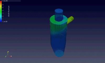
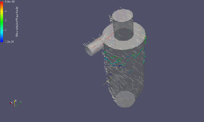
The cyclone separator's ideal condition must achieve a velocity distribution that occurs according to the picture below. A part of the cyclone wall that has contacted the particles distributed from the inlet visualized with the color according to a certain color grading. Particles would have a centrifugal force due to the cyclone's helical wall and increase its velocity with additional gravitational effect occurs to them. This gravitational effect would increase particles' acceleration and gain a greater centrifugal force within the diameter's increment, affecting each particle's mass. However, because the system is simulated using the multiphase method, there will be a vector direction difference between the phases. Due to the visualization limitations, there would be only one vector that could be visualized by the post-processor. In order to overcome this problem, the visualization would be represented using a color-graded wall based on these examples below.


