M. Reyhan Fachriansyah Hermawan
Contents
- 1 Introduction
- 2 Class Abstract
- 3 23 May 2023
- 4 30 May 2023
- 5 Design and Optimization Project - Hydrogen Tank
- 6 Project Overview
- 7 Hydrogen Gas Study
- 8 Material Choice
- 9 Geometrical Constraint
- 10 End Cap Compensation
- 11 Material Cost
- 12 3D CAD Modelling, Conclusion & Evaluation
- 13 My Conciouss Effort
- 14 ECS Class Topics Daily Summary
- 15 Centrifugal Fan
- 16 Single Blade Simulation
- 17 Force Comparison Result of Manual Calculation and Simulation
Introduction
My conciousness is my top priority
Name: M. Reyhan Fachriansyah Hermawan
NPM: 2106657172
Major: Mechanical Engineering KKI
DoB: 19 April 2003
E-mail: reyhanfachriansyah@gmail.com
Hello All!
My name is Reyhan Fachriansyah, you can call me fahri. This is my page that contains the progress of my ongoing assigned project for Numerical Method course in my fourth semester. My future goal is to establish several high-tech manufacturing company revolving around robotics, sensors, and renewable energy. I hope by undertaking this course, i will bring my self closer to my goal by expanding my knowledge and conciousness
Class Abstract
23 May 2023
This day is the first day of our course, lectured by Pak Dr. Ahmad Indra Siswantara or commonly called as "pak Dai". In this day we were given knowledge about how conciousness highly important to our daily life espescially affecting Numerical Methodology. Pak Dai also lectured us about Cara Cerdas Ingat Tuhan.
30 May 2023
On today's session, Mr. Dai assigned us to discuss together about our main project of Numerical Method with our friend Patrick Samperuru as the discussion moderator as the head of class's replacement. Each of the attendants were given several chance of public-explanation in front of the class in order to complete our project, which entails designing a functional hydrogen tank that is optimized within the constraints of pressure constraints at 8 bar, 1 liter capacity, and a maximum budget of IDR 500,000, all participants are asked to contribute their thoughts in the form of opinions and personal viewpoints. There were two session on todays dicussion, which is material discussion and optimization discussion.
The discussion was then continued by one of our friend Patrick Samperuru in the first discussion for applicable materials, Patrick then listed a number of possible materials that can be used as the hydrogen tank based on the different hydrogen tank types such as type I, (all metal), type II, (metal with a carbon fiber wrap), type III, (composite with metal lining), and type IV, (composite with non-metal lining). But for this project, he reckon that the most probable type of hydrogen tank would be the type I or II since the production would be easier, and also theoritically be able to withold 8 bar of pressure, thus the end production price will be more affordable for our capped cost of IDR 500,000. In the next turn, Reyhan Fachri stated the details of several possible material that can be applied as hydrogen tank, this inlcudes AISI 316, AISI 304, AISI 316L, AISI 304L. Cu, or Al alloys are commonly used as the main material for hydrogen tanks since it is largely immune to hydrogen effects at ambient temperatures.
For the second session of the discussion which is optimization discussion several attendee points out the three key areas required for our optimization. The area consists of design variable, goal function, and constraint, all of which may vary for each member of the class. Reyhan Fachri began by describing his objective function, which is weight consideration. In sectors like aircraft, home appliences or the automobile, where weight is particularly important, hydrogen tanks are frequently employed. Therefore, while retaining structural integrity, the tank design should strive to reduce weight. Ikhsan Rahadian then points out the importance of structural integrity to bear internal pressure, external loads, and other environmental conditions, the tank has to be structurally sound. To assure the tank's stability and strength, structural study, including finite element analysis. After that, M. Annawfal Rizky mentioned that he wanted the limitation to be the compatibility with hydrogen gas: 'The tank material should be compatible with hydrogen gas to prevent any chemical reactions, embrittlement, or degradation that could affect the tank's performance or safety', he said.
Design and Optimization Project - Hydrogen Tank
Project Overview
This design and optimization project is assigned by our lecturer Pak Dr. Ahmad Indra Siswantara as an individual project/task as a learning method to use Numerical Method as a tool for real-life application problems. The project consist of designing a hydrogen tank with some constraints: consider being the gas pressurized at 8 bars, a required volume of 1 liter, and a maximum budget of 500,000 IDR to make one. Hydrogen gas has a high level of danger espescially when pressurized to a high pressure by reason of the likelihood of explosion. Thus, it is crucial for engineers to design and optimize a safe hydrogen tanks for several type of real life practices.
When building a hydrogen storage facility, the following factors should be taken into account:
- Fatigue Resistance: Tanks must be built to sustain the necessary pressure, which is commonly expressed in bars or pounds per square inch (psi). The needed material strength, wall thickness, and structural design will be determined by the pressure rating.
- Limitations on volume and shape: The tank's overall dimensions and shape will depend on the available space and required capacity. The tank should be made to fit the area allotted for it and to have the appropriate volume.
- Material compatibility: It's important to use materials that are friendly to hydrogen since it might embrittle or have other negative effects on some materials. Carbon fiber composites, high-strength steel alloys, and several aluminum alloys are popular options.
- Weight considerations: Applications where weight is important, such in the aerospace or automobile sectors that is frequently employ hydrogen tanks inside. Therefore, while retaining structural integrity, the tank design should be able to reduce it own weight.
- Safety Features: Due to its great flammability, hydrogen demands extra safety measures. To avoid overpressurization, reduce hazards, and maintain safe operation, it is crucial to include the proper safety measures, such as pressure release devices, burst discs, and leak detection systems.
- Operational Environtment: Which includes temperature changes, exposure to moisture or chemicals, and potential impacts or vibration. The tank should be constructed so that it can resist these circumstances without losing integrity.
Hydrogen Gas Study
The lightest gas in the universe, hydrogen is often found as the diatomic gas H2, and it is typically non-reactive. However, when it is gaseous, it easily burns. Despite having a moderate reactivity, hydrogen takes up a substantial amount of space when exposed to typical circumstances like atmospheric pressure. This volume has to be decreased in order to facilitate effective storage and transit. High-pressure storage as a gas, extremely low-temperature storage as a liquid, or solid-state storage utilizing hydrides are the most used techniques for improving hydrogen storage and transit efficiency (albeit the first two techniques are more popular). Pressurization up to 700 bars or more is required to provide the greatest hydrogen output in a specific container capacity, requiring significant energy and a durable container design. Because it is cryogenic, liquid hydrogen needs to be kept at very low temperatures in order to preserve its liquid condition and avoid considerable evaporation. The attention changes away from the hydrogen yield's efficiency in the current scenario, though, where a tiny storage volume and constrained pressure are involved, to the cost and efficiency of the container material. In Indonesia, the average interior temperature is around 30 degrees Celsius, and the hydrogen gas has a density of 0.627 kilograms per cubic meter at 8 bars of pressure. Consequently, the gas weights 0.627 grams, or less than 0.001 kg, per liter, or 0.001 cubic meters. This suggests that in order to store the gas under these circumstances, a container's material and design must be able to sustain an 8 bar wall pressure. In order to guarantee that the weight of the container as a whole is much more than the weight of the gas being held, the container's density should ideally be lower.
Material Choice
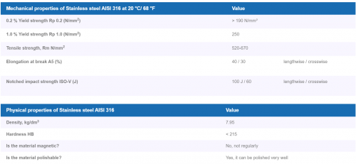
Because they can withstand the cryogenic temperatures (about -253 degrees Celsius), Type 614 austenitic stainless steels are frequently utilized for liquid hydrogen services. Austenitic stainless steels have strong ductility and energy absorption characteristics at such low temperatures, which is crucial for preserving safety. However, compared to other materials, austenitic stainless steel has a substantially lower hydrogen diffusion rate. Stainless steel outperforms other hydrogen pipeline materials in harsh situations due to its strong corrosion resistance.
Geometrical Constraint
"Geometrical constraint" refers to a restriction or requirement pertaining to the hydrogen tank's geometrical features. It outlines any restrictions or prerequisites that the tank's measurements, including its height and radius, must meet. The geomterical constraint is used to guarantee the tank's shape and capacity, optimizing its design for a particular use or objective. You are establishing the acceptable range of tank size by putting these restrictions in place. The optimization procedure then seeks to identify the ideal dimensions that reduce the thickness of the tank while satisfying other criteria like pressure limitations and material strength. The code below is the product of reviewing other geometrical constraint code from a variety of sources on the internet.
import numpy as np
from scipy.optimize import minimize
def objective(x):
   R, V = x
   h = 4 * np.sqrt((np.pi * R**2 * 4 - V) / np.pi)
   r = h / 4
   thickness = R - r
   return thickness
def volume_constraint(x):
   R, V = x
   h = 4 * np.sqrt((np.pi * R**2 * 4 - V) / np.pi)
   r = h / 4
   return np.pi * h * (R**2 - r**2) - V
def pressure_constraint(x):
   R, V = x
   t = R - (R / 4)
   stress = 8 * R / (2 * t)
   allowable_stress = 75 * 1000  # ksi to psi
   return allowable_stress - stress
# Define the initial guess for R and V in mm
x0 = np.array([100, 125])  # initial guess for R and V
# Define the bounds for R and V in mm
bounds = [(0, None), (100, 150)]
# Define the constraints
constraints = [
   {'type': 'eq', 'fun': volume_constraint},
   {'type': 'ineq', 'fun': pressure_constraint}
]
# Perform the optimization
result = minimize(objective, x0, method='SLSQP', bounds=bounds, constraints=constraints)
# Extract the optimal values
R_opt, V_opt = result.x
h_opt = 4 * np.sqrt((np.pi * R_opt**2 * 4 - V_opt) / np.pi)
r_opt = h_opt / 4
thickness_opt = R_opt - r_opt
# Print the optimal results
print('Optimal Dimensions:')
print('Outer Radius (R):', R_opt, 'cm')
print('Inner Radius (r):', r_opt, 'cm')
print('Height (h):', h_opt, 'cm')
print('Thickness:', thickness_opt, 'mm')
The code's output is displayed on the bottom left, along with the recommended shape for a cylindrical tank with a 1 liter by using AISI 614 material is:
Optimal Dimensions:
Outer Radius (R): 3.837168217663359 cm
Inner Radius (r): 3.3390053601356486 cm
Height (h): 13.356021440542595 cm
Thickness: 0.4981628575277104 mm
Volume of the tank is:
Volume = π * h * (R^2 - r^2)
Volume = π * 13.3560 * (3.837^2 - 3.339^2) cm^3
Volume ≈ 754.168 cm^3
Therefore, with the given dimensions, the volume of the cylinder is approximately 754.168 cubic millimeters (mm^3).
Surface are of the cylinder is:
A=2πrh+2πr2=2·π·3.84·13.36+2·π·3.842≈414.49885cm^2
End Cap Compensation
The bulges or convex shapes often observed on each end of gas tanks serve multiple purposes related to safety and structural integrity. Here are the main reasons why gas tanks have bulges on each end:
1. Reinforcement: Gas tanks' bulges at the ends serve as structural reinforcement. The tank becomes stronger to withstand internal and external stresses by adding curvature to the ends. This reinforcement contributes to the tank's increased longevity by boosting its resistance to deformation, impacts, and other forces.
2. Stress Distribution: The bulges help the tank's tension to be distributed more evenly. The tank's curved design helps spread the load when pressure or other external forces are applied, which lowers localized stress concentrations. The tank's resistance to deformation and probable failure under harsh conditions is improved by this design element.
3. Safety and Containment: The bulges really helps in preventing damage to the tank in the case of an accident or hit. They serve as a buffer, absorbing and dispersing forces before they enter the main body of the tank by spreading outward. By assisting in the prevention of tears or punctures, this design lowers the possibility of leaks and other possible risks related to gas containment.
It's important to note that the specific design and shape of gas tanks can vary depending on factors such as the type of gas being stored, the intended application, and safety regulations. The bulges on the ends of gas tanks are one of the common design features employed to ensure safe and reliable storage of gases.
The purpose of end cap compensation is to precisely calculate a cylindrical tank's useable capacity. The purpose is to offer accurate measurements or computations for storing liquids or other substances by taking into consideration the volume occupied by the end caps. End cap compensation makes ensuring that the quoted capacity accurately represents the volume that is really available for usage by taking the end caps' space into account. In many different industries, including engineering, manufacturing, and storage, accurate measurements are essential for effective operations and exact planning.
from scipy.integrate import quad
import numpy as np
# Function to calculate the surface area of a circle
def circle_area(radius):
   return np.pi * radius**2
# Given values
R = 3.837  # Outer Radius in mm
r = 3.339  # Inner Radius in mm
h = 13.3565  # Height in mm
thickness = 0.5  # Thickness in mm ROUNDED
# Calculate the surface area of the outer circle
A_outer, _ = quad(circle_area, 0, R)
# Calculate the surface area of the inner circle
A_inner, _ = quad(circle_area, 0, r)
# Calculate the surface area of the end cap
A_end_cap = A_outer - A_inner
# Calculate the end cap compensation
end_cap_compensation = A_end_cap * thickness
print("End Cap Compensation: {:.4f} mm^2".format(end_cap_compensation))
The final code of the end cap compensatiion result is:
End Cap Compensation: 10.0867 cm^2
Total surface area of the tank is:
414.498 + 10.0867 = 424,5847 cm^2
Material Cost
The cost of the material needed to fabricate a hydrogen tank with a surface area of 424,5847 cm^2 of stainless steel grade 316 with 5mm of thickness is listed below:
Cost of a stainless steel grade 316 plate listed on sale by Pt. Citra
Anggun Lestari for 5mm of thickness:
121,9cm × 243,8cm = 29719cm^2 = Rp. 8.099.973
We only need 424,5847 cm^2 for the tank, hence the price will be around
Rp. 116.000, that is within the budget restriction is priced
according to PT. Citra Anggun Lestari.
It is important to mention that this is not the final price to fabricate the hydrogen tank, there is much else to consider such as labor, machining cost, safety parts, and others.
3D CAD Modelling, Conclusion & Evaluation
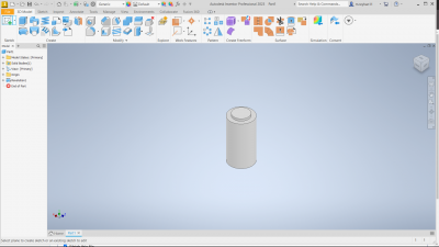
In conclusion, the use of numerical methods made it possible to calculate the hydrogen tank's dimensions in accordance with the design's strength and cost. In this case, the use of Python coding served as a facilitator for computing a variety of quantities that are based on a variety of other quantities as well as characteristics. The coding can be beneficial to our need in calculating the optimization for several condition such as Hydrogen Tank. Making the computations more precise and realistically will, in my opinion, be the greatest strategy for future advancements. It will also be a fantastic addition if we incorporate simulation, such as from ansys, solidworks, or other CAD program. There are certain presumptions that the optimization may not make the best use of, and there are some idealizations that may not be appropriate in this particular situation.
My Conciouss Effort
By the end of the project i can get some self-improvement on my self by appling my concioussness effort during all of the part of the project. I think what it means by conciusness effort is that to be aware of my own capabilities, using several tool from the open source like internet would help me improve my capabilities. But there is always some methods that is not gain-able since there is limitationto our understanding of the universe. By this project, it is important consciousness is for our daily life challenges. And by all means, i am very much grateful for all the things that god has give me.
This is the video that contain my presentation:
https://www.youtube.com/watch?v=RfFqgrKgqMg
ECS Class Topics Daily Summary
سْمِ ٱللّٰهِ ٱلرَّحْمٰنِ ٱلرَّحِيمِ
First Meeting
In our first meeting, we mainly talk about the purpose of calculus and also energy. Pak DAI mentioned about Einstein's quotes about education : What is left after you’re forgotten all you have learned. We also learned about what is calculus. One branch of mathematics that is useful for studying change is calculus. It functions similarly to a tool that helps us calculate the rate of change or the sum of items. First thing is Differentiation, This allows us to determine the rate at which something is changing at any given time. It's analogous to quickly checking the speed of an automobile. The second main thing is Integration, This aids in calculating the sum of numerous minor adjustments. It's similar to calculating a car's total available distance when you know its speed at various points in time. And for the other thing is we talked about energy. Energy is mainly talked about efficiency. Each and every energy that is beneficial to us needs to be counted in order to determine its efficiency. Since humans require energy to survive in this planet. One of the many laws of energy is that energy is convertible into other forms of energy. Logic is based on three guiding principles: the law of identity, the law of no contradiction, and the law of the middle excluded.
Second Meeting
On the date of November 1, 2023, our class convened at the DTM Computational Fluid Dynamics (CFD) Laboratory, led by Bang Edo. During this session, we delved into the world of CFD, gaining valuable insights into the intricacies of simulating fluid flows. As we gathered in the laboratory, Mr. Edo guided us through the various aspects of CFD, imparting his knowledge This immersive experience allowed us to explore and understand the dynamics of fluid behavior in a hands-on manner so it enhanced our understanding of the subject and preparing us for real-world applications of CFD in various fields. It was an enriching and intellectually stimulating class that left us with a deeper appreciation for the significance of CFD simulations in modern engineering. we talked about how engineers in the past simulate a products in terms of its efficiency and air flow. We also learned how to implement the design of Vertical Axis Wind Turbine (VAWT) and visualize it in Paraview App.
Third Meeting
On the day of November 6, 2023, we reconvened at the DTM (Department and Mechanical Engineering) laboratory, where we met our lecturer again, Mr. DAI, and our mentor Mr. Edo. This particular session was marked by a significant focus on revisiting and reflecting upon our prior progress and calculating the torque generated in our Computational Fluid Dynamics (CFD) material, particularly in relation to the Vertical Axis Wind Turbine (VAWT) simulation using Paraview and CFDSOF.
CFDSOF Simulation, Vertical Axis Wind Turbine (VAWT)
- Start time = 0
- End time = 0.1
- Inlet velocity = (6 0 0), 6 at the x axis and 0 at the y axis
Results in PARAVIEW
Pressure results
- Pressure Magnitude
The result of the pressure magnitude is presented in Figure 3.1
Figure 3.1 shows a distinct pattern where the colors denote different pressure zones: red denotes higher pressure regions and blue suggests lower pressure regions. At the turbine area, the near side of the bottom airfoil (with respect to the rotational axis) exhibits a low pressure region, while the far side (with respect to the rotational axis) exhibits a higher pressure region.
- Pressure at t = 0.02s
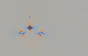 <----(Figure 3.2) The result of the Pressure at t = 0.02s is presented in Figure 3.2
- Pressure at t = 0.05s
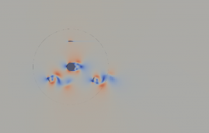 <----(Figure 3.3)The result of the Pressure at t = 0.05s is presented in Figure 3.3
- Pressure at t = 0.07s
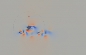 <----(Figure 3.4)The result of the Pressure at t = 0.07s is presented in Figure 3.4
- Pressure at t = 0.1s
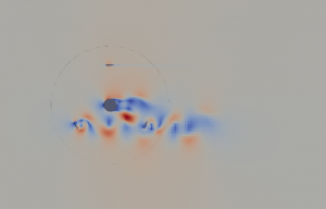 <----(Figure 3.5)The result of the Pressure at t = 0.1s is presented in Figure 3.5
Torque & Force Result
The torque and force result is presented in Figure 3.6
Velocity & Pressure Mesh Result
Static 2-Dimensional Simulation of a Single Blade
Known
- Simulation mode: Steady-state, laminar, and incompressible
- Initial condition = 0 m/s velocity
- Geometry used in the simulation: 1 m X 3 m X 1 m
- Base mesh: 10 m X 10 m X 0.1 m
- Velocity reference value: 0.01 m/s
- Simulation mode: Steady-state, laminar, and incompressible
- Initial condition = 0 m/s velocity
Centrifugal Fan
You can see the result of my work about Centrifugal fans below
Single Blade Simulation
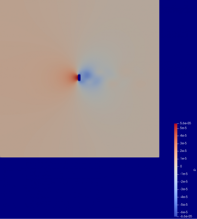
Parameters
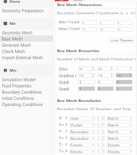
- Box geometry properties: 0.15 m X 0.4 m X 1 m
- Base mesh: 10 m X 10 m X 0.1 m at 200 X 200 X 1 division
- Velocity reference value: 0.01 m/s
- Simulation mode: Steady-state, laminar, incompressible
- Initial condition = Fixed value velocity with 0 m/s speed
Result
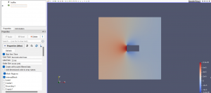
Pressure
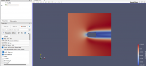
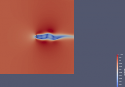
Velocity
Due to the much larger ratio between the control volume and blade size, a clear freestream region is visible outside of a certain radius of the blade.
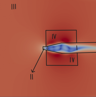
Several interesting points can be drawn from the figure above:
- This Area is called as 'Wake Region'. The blade's coverage area moves at a comparatively slow speed and has viewable turbulence. (Area 1)
- This Area is called as 'Stagnation Region'. Just in front of the blade, a tiny region has no velocity. (Area 2)
- This Area is called as 'Free-Stream Region'. There is some uniformity on the left input side. (Area 3)
- This Area is called as 'Accelerated Velocity Region'. Compared to the other places, the area above and below has the fastest velocity. (Area 4)
The increase in velocity observed in area 4 can be explained as a fundamental principle of fluid dynamics aimed at maintaining a constant flow rate within the given control volume. This principle is commonly represented by the equation Q1 = Q2, which also translates to V1 * A1 = V2 * A2. Here, Q represents the flow rate, V stands for velocity, and A denotes the area through which the fluid is flowing.
When a blade or obstruction is introduced within the flow path, it reduces the area available within the control volume. As a consequence, to uphold a consistent flow rate through the system, the velocity of the air must adapt and increase in the narrower area (Area 4 in this scenario). This adjustment in velocity is necessary to compensate for the decreased area and ensure that the same volume of air passes through the smaller area as it does through the larger area.
Therefore, the observed acceleration in the air velocity in Area 4 is a direct result of the fluid's effort to maintain a constant flow rate despite encountering a reduced space due to the obstruction. This alteration in velocity generates the distinctive shape and pattern evident in the figure, illustrating the dynamic behavior of fluids within the control volume.
Force Comparison Result of Manual Calculation and Simulation
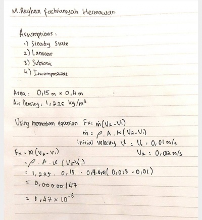
Assumptions
- Area of (0.4 * 0.15)m
- Air density of 1.225 kg/m^3
- Steady-state, laminar, incompressible
Simulation
The Force Result from the simulation is -2.13412e-6 in the X-AXIS
Manual Calculation
(Note: The Answer is in Newton [N])


