MMPIC
1.Background
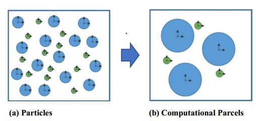
The MMPIC solids model tracks the position and trajectory of computational parcels, statistical groups of particles that share the same physical characteristics (e.g. diameter and density). In the present formulation, different diameter particles of the same material must be defined as separate solid phases, each with its own statistical classification. Figure 1 illustrates this idea.
Figure 1: Visual concept of particle consolidation to computational parcels by type. (a) A single cell populated with particles. (b) The same single cell after a statistical weight has been applied to each particle type.
If one imagines that Figure 1 represents a single cell, there are 15 blue particles represented by 3 blue computational parcels, and 12 green particles represented by 3 green computational parcels. In simple terms, 1 blue parcel carries a statistical weight of 5 particles/parcel, and 1 green parcel carries a statistical weight of 4 particles/parcel. Figure 1 one can immediately perceive the natural solution degradation that is inherent to this kind of statistical consolidation of particles. For example, the method must immediately lose the precise physics associated with particle-to-particle contacts and instead use more generalized representations of particle interactions. In particular, without resolving particle collisions or managing Newtonian mechanics in any way, the PIC model creates an aggregated solids stress momentum source term that affects local solids velocity directly. Snider (2001) refers to this source term as a frictional stress model.
The frictional stress model is driven by an evaluation of local solids volume fraction gradient and averaged field quantities. This statement implies that the model implementation is algebraic, and therefore computationally efficient. Consequently, the PIC model can deliver computational predictions for suitable large industrial applications intractable wall time. Aside from the frictional stress model, the PIC can support subsidiary models (e.g. a collisional stress model, wall friction models) that may add to the fidelity of results. As with all coupled computational fluid dynamics (CFD) simulations, these subsidiary models will add time to the solution.
2.Assumption
a. Particles are assumed spherical in shape within computational parcels. Why? Subsidiary models used in the formulation of pre-assume particles are spherical such as Wen-Yu, Gidaspow, Gidaspow-Blend, or Syamlal-O’Brien drag models, Likewise, any surface area or volume-dependent calculations rely on the radial (assumed sphere) definition, like chemical reactions.
b. Computational parcels must be defined by phase and maintain a mean density. Why? Subsidiary calculations for drag, thermal transfer, and chemical reaction rely on particle-level definitions. This allows for more simple calculations of particle diameter within each tracked parcel. For example, when density is assumed constant, and a chemical reaction takes place, a new particle diameter (within the parcel) can be calculated to reflect a mass gain/loss. Simply, accounting is easier (and faster) with this assumption.
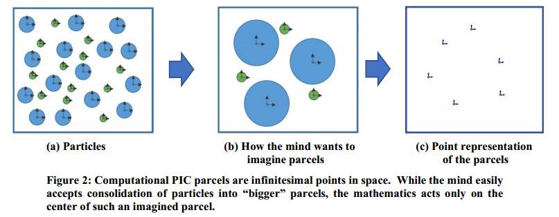
c. Computational parcels are isothermal. Why? To maintains no physical representation of how particles might populate a parcel. Mathematics treats each PIC parcel as a single point in space. There are no particle or parcel surfaces or other 3-dimensional physical features on which to act. The imagined surfaces of the computational parcels are irrelevant to the mathematical model. Figure 2 illustrates how the mind wants to give computational parcels structure
d. Computational parcels do not experience rotation. Why? Figure 2 illustrates the point representation of parcels in PIC. Points cannot experience rotation.

