JosiahEnrico
Holaaa
Perkenalkan nama saya Josiah Enrico S dari jurusan teknik mesin FTUI. Sebagai salah seorang mahasiswa, saya senang belajar dan berbagi banyak hal baru kepada dunia. Melalui wiki ini, saya akan berbagi kepada kalian tentang apa yang saya pelajari. :)
Contents
- 1 Aplikasi CFD
- 1.1 Melakukan Simulasi Tanpa Menggunakan GUI - Aplikasi Modelica/17 November 2020
- 1.2 Contoh Aplikasi Dynamic Mesh dan 6DoF - Aplikasi Modelica/19 November 2020
- 1.3 CFD Simulation for Economizer Hopper - Aplikasi Modelica/24 November 2020
- 1.4 CFD Simulation for Cyclone Separator - Aplikasi Modelica/26 November 2020
- 1.5 Project Synopsis - Aplikasi Modelica/1 Desember 2020
- 1.6 Tugas Besar CFD - Aplikasi CFD/7 November 2020 2020
- 1.7 Tugas Besar CFD - Josiah Enrico S
- 2 Metode Numerik
- 2.1 Intro - Metode Numerik/11 November 2020
- 2.2 Aplikasi Modelica - Metode Numerik/18 November 2020
- 2.3 Fungsi Panggil dalam Modelica - Metode Numerik/18 November 2020
- 2.4 Finite Element Method for Trusses - Metode Numerik/2 Desember 2020
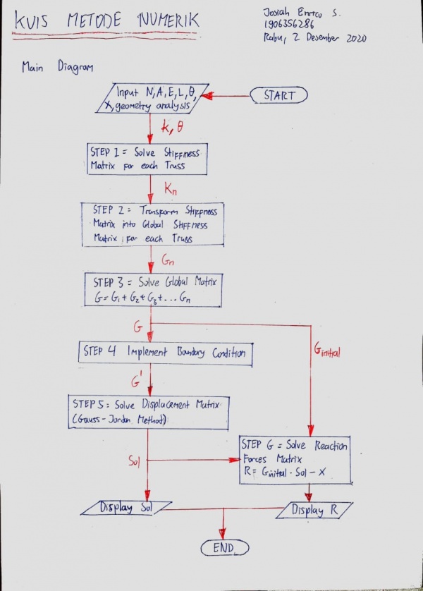
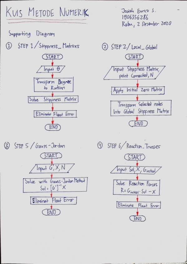
- 2.5 Kuis Membuat Class FLowchart - Metode Numerik/18 November 2020
- 2.6 3D Trusses - Metode Numerik/18 November 2020
- 2.7 Gate Valve - Aplikasi CFD/12 November 2020
Aplikasi CFD
Melakukan Simulasi Tanpa Menggunakan GUI - Aplikasi Modelica/17 November 2020
Contoh Aplikasi Dynamic Mesh dan 6DoF - Aplikasi Modelica/19 November 2020
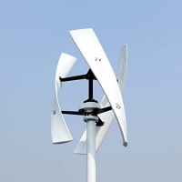
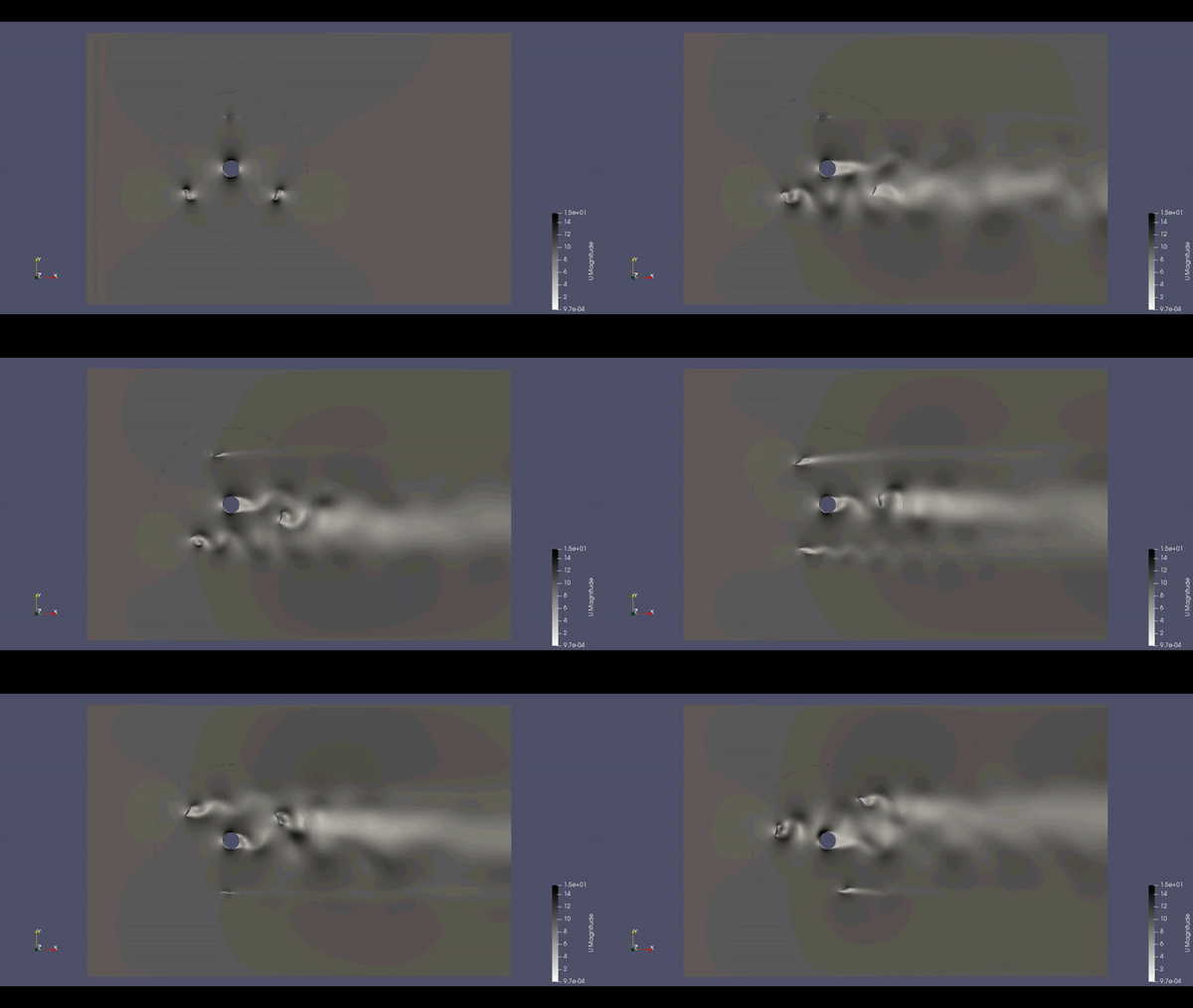
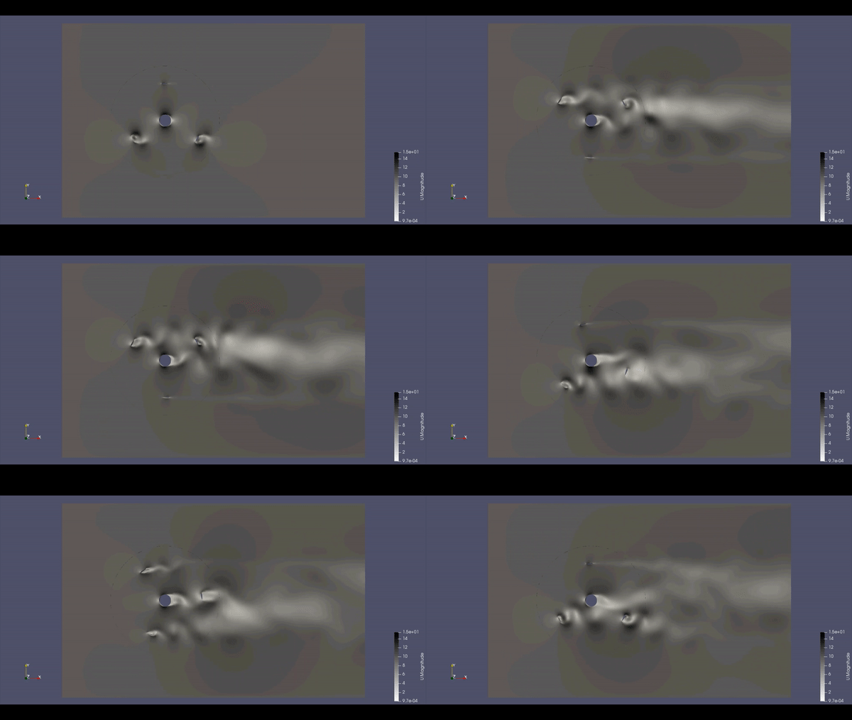
VAWT atau singkatan dari Vertical Axis Wind Turbin adalah salah satu mesin tenaga yang mengubah energi mekanis dari aliran angin menjadi kerja. ciri khas mesin tipe ini adalah turbin memiliki poros yang tegak lurus dengan aliran fluida dan vertikal dengan tanah seperti gambar di samping. Desain ini memungkinkan aliran angin dari arah manapun dapat dimanfaatkan untuk menjadi kerja asalkan tidak sejajar dengan poros turbin ini. Dalam insdustri, mesin ini juga dikenal sebagai "transverse axis wind turbine" atau "cross-flow wind turbine." Dalam artikel ini, diperlihatkan simulasi komputer yang menggambarkan dinamika fluida ketika turbin sedang beroperasi (dengan variasi massa jenis).
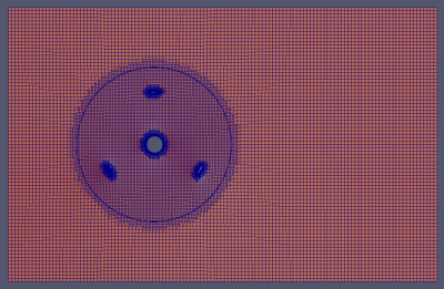
Untuk mengimplementasikan simulasi CFD dalam desain berikut, digunakan metode Dynamic Mesh dan 6DoF (6 Degree of Freedom). Dynamic Mesh berarti mesh tidak rigid tapi fleksibel misalnya bergerak dalam suatu jalur atau berputar dalam suatu axis, sedangkan 6DoF berarti simulasi dilakukan dengan memperhatikan kebebasan gerak suatu mesh ketika dialiri fluida (Dalam 3 dimensi kebebasan ini berderajat 6)
|
|
| rho=1,2 kg/m^3 | rho=4.8 kg/m^3 |
Analisa
CFD Simulation for Economizer Hopper - Aplikasi Modelica/24 November 2020
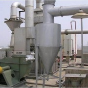
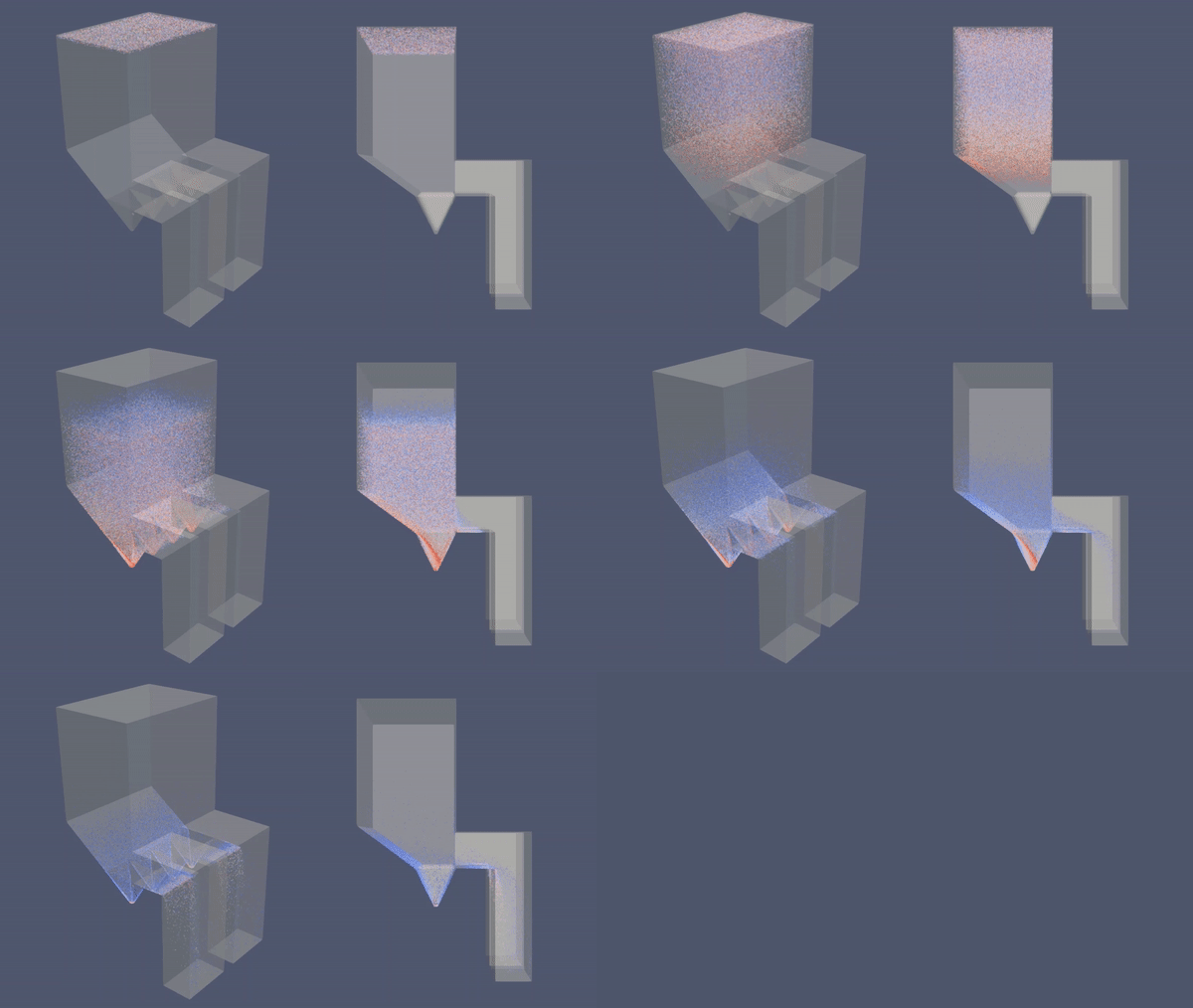
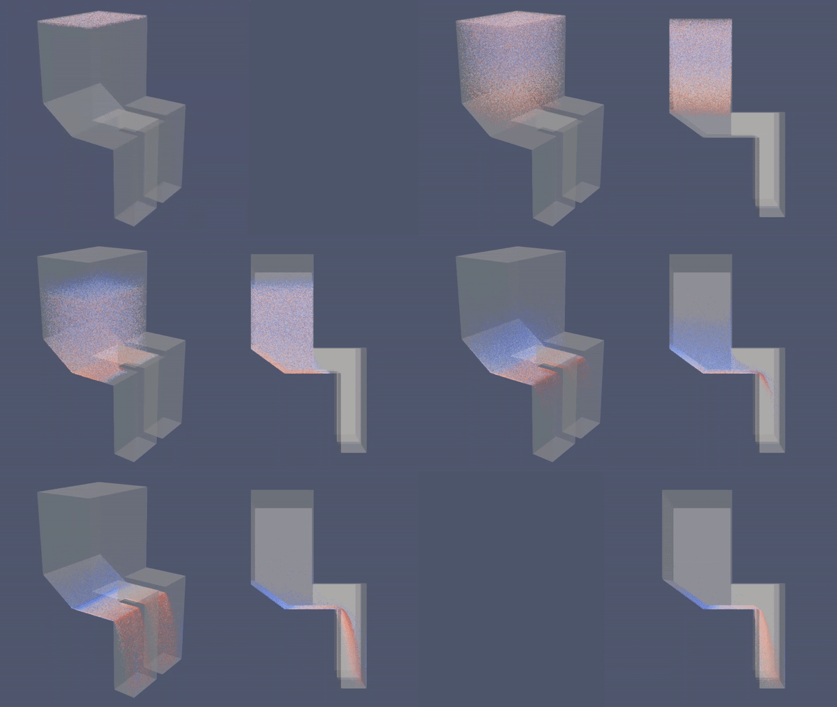
Economizer Hopper adalah salah satu fitur ducting yang biasanya terdapat dalam PLTU yang menggunakan batu bara. Fitur ini berfungsi menangkap dan menampung fly ash (abu terbang) yang dihasilkan pembakaran batu bara. Tanpa Economizer Hopper, debu tersebut bisa menimbulkan berbagai masalah operasional seperti menghambat aliran fluida di preheater, merusak blade IDF dan Guide Vane, menumpuk di ducting dan bahkan juga mencemari lingkungan. Dalam artikel ini, akan ditunjukkan simulasi CFD yang menggambarkan perbedaan efektifitas sistem yang menggunakan Economizer Hopper dan tanpa Hopper.
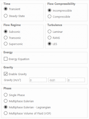
- Model Simulasi dalam CFD:
- 3D
- Transient
- Incompressible
- Turbulent
- No Heat Transfer
- Multi-phase
|
|
| Economizer dengan Hopper | Economizer tanpa Hopper |
- Analisa:
CFD Simulation for Cyclone Separator - Aplikasi Modelica/26 November 2020
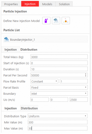
Cyclone separators or simply cyclones are separation devices (dry scrubbers) that use the principle of inertia to remove particulate matter from flue gases. Cyclone separators is one of many air pollution control devices known as pre-cleaners since they generally remove larger pieces of particulate matter. This prevents finer filtration methods from having to deal with large, more abrasive particles later on. In addition, several cyclone separators can operate in parallel, and this system is known as a multi-cyclone.
It is important to note that cyclones can vary drastically in their size. The size of the cyclone depends largely on how much flue gas must be filtered, thus larger operations tend to need larger cyclones. For example, several different models of one cyclone type can exist, and the sizes can range from a relatively small 1.2-1.5 meters tall to around 9 meters —which is about as tall as a three-story building.
source: https://energyeducation.ca/encyclopedia/Cyclone_separator
Verification:
Validation:
- Effect of Air-Particle Density Difference
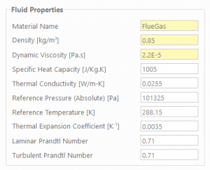
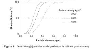
- Air-particle density difference (ρp − ρg) is a key parameter in cyclone efficiency calculations. Efficiency prediction by Li and Wang modified model for different particle density is shown in Figure 4. The numerical simulation result shows that the critical particle size, dpc, for particle with density 3000 kg/m3 is around 2.2 µm and is around 4.2 µm for 1000 kg/m3 particle density. A bigger particle density tends to result in a larger air-particle density difference since the air density remains constant. Bigger air-particle density difference led to a higher resultant centrifugal force acting on the particle, and the higher centrifugal force in cyclone has led to higher separation efficiency. It can be concluded from this finding that the bigger the particle density is, the smaller the critical particle size (dpc) would be obtained, or by other means, the sharper the separations would be.
- Effect of Inlet Velocity
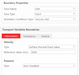
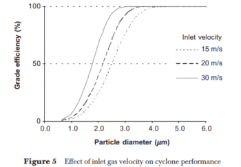
- Inlet gas velocity, vi, is an important factor for cyclone sizing in order to achieve a desired separation efficiency. Inlet cyclone velocity is a result of dividing the inlet gas flow rate, Q, to the cyclone inlet area (a.b). At a high flow rate, the inlet velocity becomes larger thus, the tangential velocity, vi, also increases. The cut-off diameter varies inversely with the square root of the inlet velocity. The effect of inlet velocity to the cyclone performance is shown in Figure 5. It shows that for the identical size and configuration of cyclone, the higher the gas inlet velocity is, the sharper the efficiency would be. However, a very high inlet velocity would decrease the collection efficiency because of increased turbulence and saltation/re-entrainment of particles. Shepherd and Lapple recommended that the optimum cyclone operating velocity is around 18 m/s. However, the range of practicable cyclone inlet velocity is around 15 – 30 m/s.
Simulation Result:
Analysis:
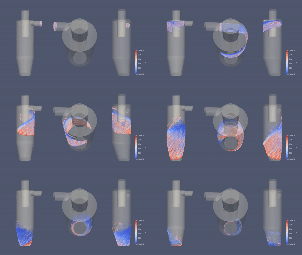
As we can see in the simulation above, the geometry of the cyclone separator will generate swiveling fluid inside the cylinder. This cyclone-like flow is started by the tangential velocity of fluid entering the inlet of the chamber. While whirling along the chamber surface, gravity takes place by driving the multiphase stream downward creating a vortex. Since larger particles tend to have heavier mass relative to the density and worse compliant to the high-speed spiral motion of the vortex, the particles hit the inside walls, lose momentum, and drop down into the bottom of the container. In reverse, the cleaner gas or fluid with smaller particles (blue particles) go along the cone-shaped wall following the high-speed movement of the vortex, float upward and escape out the top of the chamber. This effect is also related to the inertia of every particle itself, less for the smaller particulate and more for the larger ones. Unfortunately, we cannot see the complete upward movement of smaller particles as the duration of the simulation is not long enough respectively, but at the end of the illustration, we may see a glimpse of those particulates (blue particle) are raising upward.
Project Synopsis - Aplikasi Modelica/1 Desember 2020
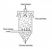
As elutriator, or an apparatus used to separate suspended solid particles according to size, have been used in the plastic industry regarding dust particles such as streamer or angel hair elimination, there is a need to observe the effectiveness of this control process to produce cleaner plastic pellet. In doing so theoretically, some recent studies show differences in particle size are exploited when they are subjected to an upward flowing current of fluid, leading to separation into size-based underflow and overflow streams. The tendency of a particle to report to either stream is dependent on its terminal sedimentation velocity, as well as the upward velocity of the fluid. Where the terminal velocity exceeds the fluid velocity, the particle will settle against the current and report to the underflow and vice versa. This research will recreate the flow using computational fluid dynamics application to help us understand the variation of particle size or density of particles leading to different sedimentation velocities in the separation process.
Tugas Besar CFD - Aplikasi CFD/7 November 2020 2020
Tugas Besar CFD - Josiah Enrico S
Metode Numerik
Intro - Metode Numerik/11 November 2020
Tujuan belajar metode numerik yaitu agar penulis dapat:
1) Memahami konsep dan prinsip dasar metode numerik.
2) Memahami aplikasi metode numerik
3) Menyelesaikan persoalan teknik dengan metoda numerik
4) Mendapat nilai tambah sebagai manusia yang lebih beradab
Aplikasi Modelica - Metode Numerik/18 November 2020
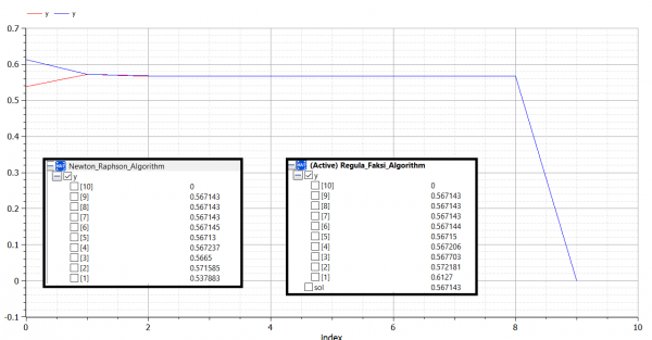
Berikut ini adalah contoh penerapan aplikasi OpenModelica untuk membuat 4 algoritma metode numerik dalam mencari roots of equation (akar persamaan) dari:
f(x) = exp^(-x)-(x)
f'(x) = -exp^(-x)-1
error maksimum = 0.0000001
1) Newton Raphson (Terbuka)
model Newton_Raphson_Algorithm

parameter Real g=1; //guess
parameter Integer N=20; //max iteration
parameter Real er=0.0000001; //error maximum
Real a[N];
Real y[N];//function
Real ER[N]; //error
Real sol; //solution

algorithm

a[1]:=g;
y[1]:=a[1]-(exp(-a[1])-a[1])/(-exp(-a[1])-1);
ER[1]:=abs(1-a[1]/y[1]);

for i in 2:N loop
  a[i]:=y[i-1];
  y[i]:=a[i]-(exp(-a[i])-a[i])/(-exp(-a[i])-1);
  ER[i]:=abs(1-y[i-1]/y[i]);

  if ER[i]<er then
 sol:=y[i];
 break;
 end if;
end for;

end Newton_Raphson_Algorithm;
2) Secant (Terbuka)
model Secant_Algorithm

parameter Real a=0; //guess
parameter Real b=1; //guess
parameter Integer N=10; //max iteration
parameter Real er=0.0000001; //error maximum
Real A[N];
Real B[N];
Real y[N];
Real ER[N];
Real sol; //solution

algorithm

A[1]:=a;
B[1]:=b;
y[1]:=B[1]-(exp(-B[1])-B[1])*(A[1]-B[1])/((exp(-A[1])-A[1])-(exp(-B[1])-B[1]));
ER[1]:=abs(1-B[1]/y[1]);

for i in 2:N loop
 A[i]:=B[i-1];
 B[i]:=y[i-1];
 y[i]:=B[i]-(exp(-B[i])-B[i])*(A[i]-B[i])/((exp(-A[i])-A[i])-(exp(-B[i])-B[i]));
 ER[i]:=abs(1-y[i-1]/y[i]);

 if ER[i]<er then
 sol:=y[i];
 break;

 end if;
end for;

end Secant_Algorithm;
3) Bisection (Tertutup)
model Bisection_Algorithm

parameter Real a=0; //guess bawah
parameter Real b=1; //guess atas
parameter Integer N=50; //max iteration
parameter Real er=0.0000001; //error maximum
Real fa=(exp(-a)-a);
Real fb=(exp(-b)-b);
Real A[N];
Real B[N];
Real fy[N];
Real y[N];
Real ER[N];
Real sol; //solution

algorithm

if fa*fb<0 then

A[1]:=a;
B[1]:=b;
y[1]:=(A[1]+B[1])/2;
fy[1]:=exp(-y[1])-y[1];
ER[1]:=1;

for i in 2:N loop
 if fy[i-1]>0 then
 A[i]:=y[i-1];
 B[i]:=B[i-1];
 else
 A[i]:=A[i-1];
 B[i]:=y[i-1];
 end if;

 y[i]:=(A[i]+ B[i])/2;
 fy[i]:=exp(-y[i])-y[i];
 ER[i]:=abs(1-y[i-1]/y[i]);

 if ER[i]<er then
 sol:=y[i];
 break;
 end if;

end for;
end if;

end Bisection_Algorithm;
4) Regula Falsi (Tertutup)
model Regula_Falsi_Algorithm

parameter Real a=0; //guess bawah
parameter Real b=1; //guess atas
parameter Integer N=20; //max iteration
parameter Real er=0.0000001; //error maximum
Real A[N];
Real B[N];
Real fa[N];
Real fb[N];
Real fy[N];
Real y[N];
Real ER[N];
Real sol; //solution

algorithm

A[1]:=a;
B[1]:=b;
fa[1]:=exp(-A[1])-A[1];
fb[1]:=exp(-B[1])-B[1];

if fa[1]*fb[1]<0 then

y[1]:=(A[1]*fb[1]-B[1]*fa[1])/(fb[1]-fa[1]);
fy[1]:=exp(-y[1])-y[1];
ER[1]:=1;

for i in 2:N loop
 if fy[i-1]>0 then
 A[i]:=y[i-1];
 B[i]:=B[i-1];
 else
 A[i]:=A[i-1];
 B[i]:=y[i-1];
 end if;

 fa[i]:=exp(-A[i])-A[i];
 fb[i]:=exp(-B[i])-B[i];
 y[i]:=(A[i]*fb[i]-B[i]*fa[i])/(fb[i]-fa[i]);
 fy[i]:=exp(-y[i])-y[i];
 ER[i]:=abs(1-y[i-1]/y[i]);

 if ER[i]<er then
 sol:=y[i];
 break;
 end if;
end for;
end if;

end Regula_Falsi_Algorithm;
Berikut link Youtube yang berisi penjelasan tentang algoritma dan penulisan kode OpenModelica keempat metode diatas:
Fungsi Panggil dalam Modelica - Metode Numerik/18 November 2020
Fungsi panggil dalam aplikasi Modelica adalah metode membuat fungsi numerik dalam kelas function yang akan digunakan di dalam permodelan numerik utama (tipe 'class'). metode ini biasanya dipakai untuk menyederhanakan persoalan matematika yang kompleks, seperti persamaan aljabar simultan, sehingga lebih mudah diselesaikan. Dalam artikel ini akan ditampilkan 3 contoh persoalan numerik dengan solusi array atau lebih dari satu anggota:
1) Root of Equation (Newton Raphson dan Regula Falsi)
|
Newton Raphson ... algorithm a[1]:=g; y[1]:=a[1]-(Fungsi(a[1]))/(Der_Fungsi(a[1])); ER[1]:=abs(1-a[1]/y[1]); for i in 2:N loop a[i]:=y[i-1]; y[i]:=a[i]-(Fungsi(a[i]))/(Der_Fungsi(a[1])); ER[i]:=abs(1-y[i-1]/y[i]); if ER[i]<er then sol:=y[i]; break; end if; Regula Falsi ... fa[1]:=Fungsi(A[1]); fb[1]:=Fungsi(B[1]); if fa[1]*fb[1]<0 then y[1]:=(A[1]*fb[1]-B[1]*fa[1])/(fb[1]-fa[1]); fy[1]:=Fungsi(y[1]); ER[1]:=1; ... fa[i]:=Fungsi(A[i]); fb[i]:=Fungsi(B[i]); y[i]:=(A[i]*fb[i]-B[i]*fa[i])/(fb[i]-fa[i]); fy[i]:=Fungsi(y[i]); ER[i]:=abs(1-y[i-1]/y[i]); ... |
fungsi function Fungsi input Real X; output Real Y; algorithm Y:=exp(-X)-X; end Fungsi; fungsi turunan function Der_Fungsi input Real X; output Real Y; algorithm Y:=-exp(-X)-1; end Der_Fungsi; |
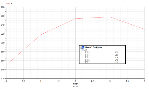
2) Heat Diffusion
Referensi: Versteeg, H. K., Malalasekera, W. (2007). An Introduction to Computational Fluid Dynamics. 2nd Edition. Harlow: Pearson (Example 4.2)
|
Persamaan class TesAljabar
parameter Real A[5,5]=[375,-125,0,0,0;
-125,250,-125,0,0;
0,-125,250,-125,0;
0,0,-125,250,-125;
0,0,0,-125,375];
parameter Real B[5]={29000,4000,4000,4000,54000};
Real X[5];
equation
X=matriks5(A,B);
end TesAljabar;
|
fungsi function matriks5 input Real A[5,5]; input Real B[5]; output Real X[5]; algorithm X:=Modelica.Math.Matrices.solve(A,B); end matriks5; |
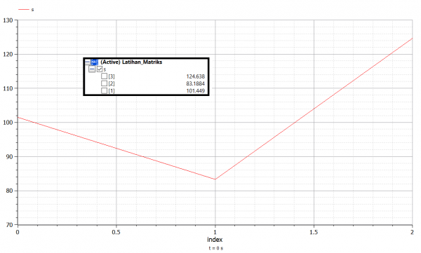
3) Combined Spring Stiffness
Referensi: http://www.sharetechnote.com/html/EngMath_Matrix_FEM_ComplicatedSpring.html
|
Persamaan class Latihan_Matriks
parameter Real c1=1; //spring 1
parameter Real c2=2; //spring 2
parameter Real c3=3; //spring 3
parameter Real c4=4; //spring 4
parameter Real c5=5; //spring 5
parameter Real k1[3,3]=c1*[1,0,0;
0,0,0;
0,0,0];
parameter Real k2[3,3]=c2*[1,-1,0;
-1,1,0;
0,0,0];
parameter Real k3[3,3]=c3*[1,-1,0;
-1,1,0;
0,0,0];
parameter Real k4[3,3]=c4*[1,0,-1;
0,0,1;
-1,0,1];
parameter Real k5[3,3]=c5*[0,0,0;
0,1,-1;
0,-1,1];
parameter Real B[3]={100,200,300};
Real K[3,3];
Real s[3];
algorithm
K:=k1+k2+k3+k4+k5;
s:=matriks3(K,B);
end Latihan_Matriks;
|
fungsi function matriks3 input Real A[3,3]; input Real B[3]; output Real X[3]; algorithm X:=Modelica.Math.Matrices.solve(A,B); end matriks3; |
Berikut link Youtube yang berisi penjelasan tentang algoritma dan penulisan kode OpenModelica latihan diatas:
Berikut juga adalah pemodelan Modelica untuk metode Naive Gauss:
Finite Element Method for Trusses - Metode Numerik/2 Desember 2020
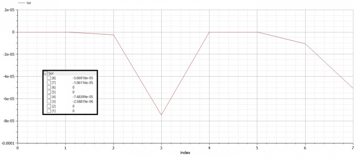
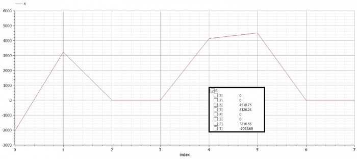
Berikut 2 contoh penggunaan aplikasi Modelica untuk menyelesaikan perhitungan displacement dan reaction force pada trusses:
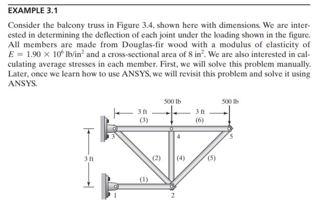
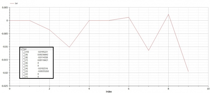
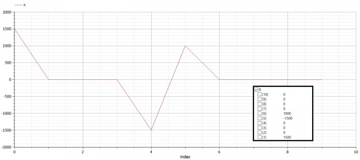
Trusses Problem 1 (Example 3.1)
|
Persamaan model Trusses
parameter Integer N=10; //Global matrice = 2*points connected
parameter Real A=8;
parameter Real E=1.9e6;
Real G[N,N]; //global
Real Ginitial[N,N]; //global
Real Sol[N]; //global dispplacement
Real X[N]={0,0,0,0,0,0,0,-500,0,-500};
Real R[N]; //global reaction force
Real SolMat[N,1];
Real XMat[N,1];
//boundary coundition
Integer b1=1;
Integer b2=3;
//truss 1
parameter Real X1=0; //degree between truss
Real k1=A*E/36;
Real K1[4,4]; //stiffness matrice
Integer p1a=1;
Integer p1b=2;
Real G1[N,N];
//truss 2
parameter Real X2=135; //degree between truss
Real k2=A*E/50.912;
Real K2[4,4]; //stiffness matrice
Integer p2a=2;
Integer p2b=3;
Real G2[N,N];
//truss 3
parameter Real X3=0; //degree between truss
Real k3=A*E/36;
Real K3[4,4]; //stiffness matrice
Integer p3a=3;
Integer p3b=4;
Real G3[N,N];
//truss 4
parameter Real X4=90; //degree between truss
Real k4=A*E/36;
Real K4[4,4]; //stiffness matrice
Integer p4a=2;
Integer p4b=4;
Real G4[N,N];
//truss 5
parameter Real X5=45; //degree between truss
Real k5=A*E/50.912;
Real K5[4,4]; //stiffness matrice
Integer p5a=2;
Integer p5b=5;
Real G5[N,N];
//truss 6
parameter Real X6=0; //degree between truss
Real k6=A*E/36;
Real K6[4,4]; //stiffness matrice
Integer p6a=4;
Integer p6b=5;
Real G6[N,N];
/*
for each truss, please ensure pXa is lower then pXb (X represents truss element number)
*/
algorithm
//creating global matrice
K1:=Stiffness_Matrices(X1);
G1:=k1*Local_Global(K1,N,p1a,p1b);
K2:=Stiffness_Matrices(X2);
G2:=k2*Local_Global(K2,N,p2a,p2b);
K3:=Stiffness_Matrices(X3);
G3:=k3*Local_Global(K3,N,p3a,p3b);
K4:=Stiffness_Matrices(X4);
G4:=k4*Local_Global(K4,N,p4a,p4b);
K5:=Stiffness_Matrices(X5);
G5:=k5*Local_Global(K5,N,p5a,p5b);
K6:=Stiffness_Matrices(X6);
G6:=k6*Local_Global(K6,N,p6a,p6b);
G:=G1+G2+G3+G4+G5+G6;
Ginitial:=G;
//implementing boundary condition
for i in 1:N loop
G[2*b1-1,i]:=0;
G[2*b1,i]:=0;
G[2*b2-1,i]:=0;
G[2*b2,i]:=0;
end for;
G[2*b1-1,2*b1-1]:=1;
G[2*b1,2*b1]:=1;
G[2*b2-1,2*b2-1]:=1;
G[2*b2,2*b2]:=1;
//solving displacement
Sol:=Gauss_Jordan(N,G,X);
//solving reaction force
SolMat:=matrix(Sol);
XMat:=matrix(X);
R:=Reaction_Trusses(N,Ginitial,SolMat,XMat);
end Trusses;
|
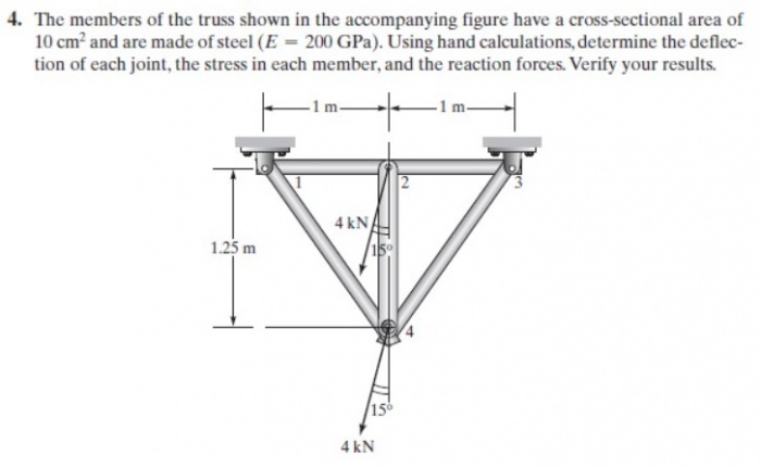
Trusses Problem 2 (Homework)
|
Persamaan class Trusses_HW
parameter Integer N=8; //Global matrice = 2*points connected
parameter Real A=0.001; //Area m2
parameter Real E=200e9; //Pa
Real G[N,N]; //global
Real Ginitial[N,N]; //global
Real Sol[N]; //global dispplacement
Real X[N]={0,0,-1035.2762,-3863.7033,0,0,-1035.2762,-3863.7033};
Real R[N]; //global reaction force
Real SolMat[N,1];
Real XMat[N,1];
//boundary condition
Integer b1=1;
Integer b2=3;
//truss 1
parameter Real X1=0; //degree between truss
Real k1=A*E/1;
Real K1[4,4]; //stiffness matrice
Integer p1a=1;
Integer p1b=2;
Real G1[N,N];
//truss 2
parameter Real X2=0; //degree between truss
Real k2=A*E/1;
Real K2[4,4]; //stiffness matrice
Integer p2a=2;
Integer p2b=3;
Real G2[N,N];
//truss 3
parameter Real X3=90; //degree between truss
Real k3=A*E/1.25;
Real K3[4,4]; //stiffness matrice
Integer p3a=2;
Integer p3b=4;
Real G3[N,N];
//truss 4
parameter Real X4=90+38.6598; //degree between truss
Real k4=A*E/1.6;
Real K4[4,4]; //stiffness matrice
Integer p4a=1;
Integer p4b=4;
Real G4[N,N];
//truss 5
parameter Real X5=90-38.6598; //degree between truss
Real k5=A*E/1.6;
Real K5[4,4]; //stiffness matrice
Integer p5a=3;
Integer p5b=4;
Real G5[N,N];
/*
for each truss, please ensure pXa is lower then pXb (X represents truss element number)
*/
algorithm
//creating global matrice
K1:=Stiffness_Matrices(X1);
G1:=k1*Local_Global(K1,N,p1a,p1b);
K2:=Stiffness_Matrices(X2);
G2:=k2*Local_Global(K2,N,p2a,p2b);
K3:=Stiffness_Matrices(X3);
G3:=k3*Local_Global(K3,N,p3a,p3b);
K4:=Stiffness_Matrices(X4);
G4:=k4*Local_Global(K4,N,p4a,p4b);
K5:=Stiffness_Matrices(X5);
G5:=k5*Local_Global(K5,N,p5a,p5b);
G:=G1+G2+G3+G4+G5;
Ginitial:=G;
//implementing boundary condition
for i in 1:N loop
G[2*b1-1,i]:=0;
G[2*b1,i]:=0;
G[2*b2-1,i]:=0;
G[2*b2,i]:=0;
end for;
G[2*b1-1,2*b1-1]:=1;
G[2*b1,2*b1]:=1;
G[2*b2-1,2*b2-1]:=1;
G[2*b2,2*b2]:=1;
//solving displacement
Sol:=Gauss_Jordan(N,G,X);
//solving reaction force
SolMat:=matrix(Sol);
XMat:=matrix(X);
R:=Reaction_Trusses(N,Ginitial,SolMat,XMat);
end Trusses_HW;
|
Fungsi Panggil
|
Matrice Transformation function Stiffness_Matrices
input Real A;
Real Y;
output Real X[4,4];
Real float_error = 10e-10;
final constant Real pi=2*Modelica.Math.asin(1.0);
algorithm
Y:=A/180*pi;
X:=[(Modelica.Math.cos(Y))^2,Modelica.Math.cos(Y)*Modelica.Math.sin(Y),-(Modelica.Math.cos(Y))^2,-Modelica.Math.cos(Y)*Modelica.Math.sin(Y);
Modelica.Math.cos(Y)*Modelica.Math.sin(Y),(Modelica.Math.sin(Y))^2,-Modelica.Math.cos(Y)*Modelica.Math.sin(Y),-(Modelica.Math.sin(Y))^2;
-(Modelica.Math.cos(Y))^2,-Modelica.Math.cos(Y)*Modelica.Math.sin(Y),(Modelica.Math.cos(Y))^2,Modelica.Math.cos(Y)*Modelica.Math.sin(Y);
-Modelica.Math.cos(Y)*Modelica.Math.sin(Y),-(Modelica.Math.sin(Y))^2,Modelica.Math.cos(Y)*Modelica.Math.sin(Y),(Modelica.Math.sin(Y))^2];
for i in 1:4 loop
for j in 1:4 loop
if abs(X[i,j]) <= float_error then
X[i,j] := 0;
end if;
end for;
end for;
end Stiffness_Matrices;
|
Global Element Matrice function Local_Global
input Real Y[4,4];
input Integer B;
input Integer p1;
input Integer p2;
output Real G[B,B];
algorithm
for i in 1:B loop
for j in 1:B loop
G[i,j]:=0;
end for;
end for;
G[2*p1,2*p1]:=Y[2,2];
G[2*p1-1,2*p1-1]:=Y[1,1];
G[2*p1,2*p1-1]:=Y[2,1];
G[2*p1-1,2*p1]:=Y[1,2];
G[2*p2,2*p2]:=Y[4,4];
G[2*p2-1,2*p2-1]:=Y[3,3];
G[2*p2,2*p2-1]:=Y[4,3];
G[2*p2-1,2*p2]:=Y[3,4];
G[2*p2,2*p1]:=Y[4,2];
G[2*p2-1,2*p1-1]:=Y[3,1];
G[2*p2,2*p1-1]:=Y[4,1];
G[2*p2-1,2*p1]:=Y[3,2];
G[2*p1,2*p2]:=Y[2,4];
G[2*p1-1,2*p2-1]:=Y[1,3];
G[2*p1,2*p2-1]:=Y[2,3];
G[2*p1-1,2*p2]:=Y[1,4];
end Local_Global;
|
Reaction Matrice Equation function Reaction_Trusses input Integer N; input Real A[N,N]; input Real B[N,1]; input Real C[N,1]; Real X[N,1]; output Real Sol[N]; Real float_error = 10e-10; algorithm X:=A*B-C; for i in 1:N loop if abs(X[i,1]) <= float_error then X[i,1] := 0; end if; end for; for i in 1:N loop Sol[i]:=X[i,1]; end for; end Reaction_Trusses; Gauss Jordan function Gauss_Jordan input Integer N; input Real A[N,N]; input Real B[N]; output Real X[N]; Real float_error = 10e-10; algorithm X:=Modelica.Math.Matrices.solve(A,B); for i in 1:N loop if abs(X[i]) <= float_error then X[i] := 0; end if; end for; end Gauss_Jordan; |
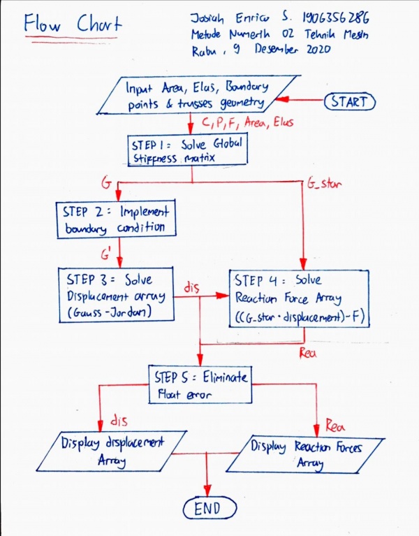
Kuis Membuat Class FLowchart - Metode Numerik/18 November 2020
3D Trusses - Metode Numerik/18 November 2020
|
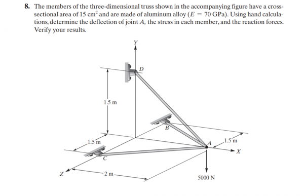
Master class Trusses3D_Tes
//define initial variable
parameter Integer Points=4; //Number of Points
parameter Integer Trusses=3; //Number of Trusses
parameter Real Area=0.0015; //Area
parameter Real Elas=70e9; //Elasticity
//define connection
parameter Integer C[Trusses,2]=[1,2;
1,3;
1,4];
//define coordinates (please put orderly)
parameter Real P[Points,3]=[2,0,0;
0,0,1.5;
0,0,-1.5;
0,1.5,0];
//define external force (please put orderly)
parameter Real F[Points*3]={0,-5000,0,
0,0,0,
0,0,0,
0,0,0};
//define boundary
parameter Integer b[:]={2,3,4};
//solution
Real displacement[N], reaction[N];
protected
parameter Integer N=3*Points;
Integer boundary[3*size(b,1)]=cat(1,(3*b).-2,(3*b).-1,3*b);
Real q1[3], q2[3], g[N,N], G[N,N], G_star[N,N], id[N,N]=identity(N), err=10e-10, cx, cy, cz, L, X[3,3];
algorithm
//Creating Global Matrix
G:=id;
for i in 1:Trusses loop
for j in 1:3 loop
q1[j]:=P[C[i,1],j];
q2[j]:=P[C[i,2],j];
end for;
       //Solving Matrix
       L:=Modelica.Math.Vectors.length(q2-q1);
       cx:=(q2[1]-q1[1])/L;
       cy:=(q2[2]-q1[2])/L;
       cz:=(q2[3]-q1[3])/L;
       X:=(Area*Elas/L)*[cx^2,cx*cy,cx*cz;
                         cy*cx,cy^2,cy*cz;
                         cz*cx,cz*cy,cz^2];

       //Transforming to global matrix
       g:=zeros(N,N);
       for m,n in 1:3 loop
         g[3*(C[i,1]-1)+m,3*(C[i,1]-1)+n]:=X[m,n];
         g[3*(C[i,2]-1)+m,3*(C[i,2]-1)+n]:=X[m,n];
         g[3*(C[i,2]-1)+m,3*(C[i,1]-1)+n]:=-X[m,n];
         g[3*(C[i,1]-1)+m,3*(C[i,2]-1)+n]:=-X[m,n];
       end for;

 G_star:=G+g;
 G:=G_star;
end for;

//Implementing boundary
for i in boundary loop
 for j in 1:N loop
   G[i,j]:=id[i,j];
 end for;
end for;

//Solving displacement
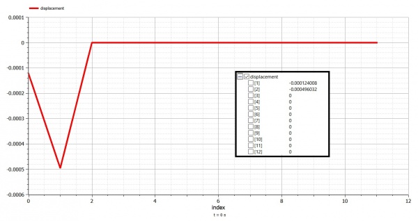
displacement:=Modelica.Math.Matrices.solve(G,F);

//Solving reaction
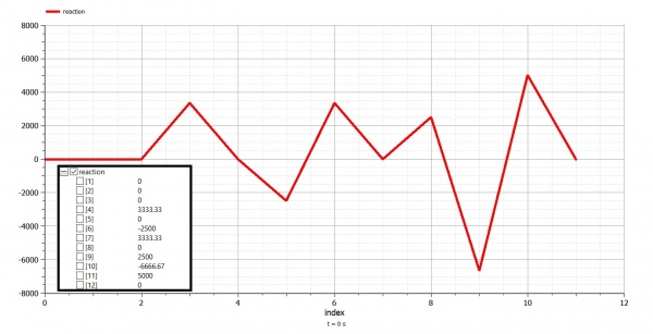
reaction:=(G_star*displacement)-F;

//Eliminating float error
for i in 1:N loop
 reaction[i]:=if abs(reaction[i])<=err then 0 else reaction[i];
 displacement[i]:=if abs(displacement[i])<=err then 0 else displacement[i];
end for;

end Trusses3D_Tes;
|
Gate Valve - Aplikasi CFD/12 November 2020
Gate Valve
membuka atau menutup aliran
Mengatur kecepataan fluida (Regulasi)
Mangatasi Backflow atau aliran balik

