Difference between revisions of "Vegantra Amayko Siaga"
(→Conclusion) |
(→Steam Turbine Experiment) |
||
| (9 intermediate revisions by the same user not shown) | |||
| Line 326: | Line 326: | ||
== Steam Turbine Experiment == | == Steam Turbine Experiment == | ||
| + | |||
| + | https://www.youtube.com/watch?v=toUOzvxt8HU | ||
=== Basic Theory === | === Basic Theory === | ||
| Line 331: | Line 333: | ||
[[File:Turbine_Rankine_Cycle.png|100x100]] | [[File:Turbine_Rankine_Cycle.png|100x100]] | ||
| + | [[File:fotosteam.jpg|50x50]] | ||
=== Calculation === | === Calculation === | ||
| Line 368: | Line 371: | ||
Efficiency : 7,8% | Efficiency : 7,8% | ||
| − | === Conclusion === | + | === Conclusion and My Consiousness Effort === |
| − | The system's efficiency is relatively low, approximately 7.81%. Nevertheless, this figure isn't unfavorable due to the use of basic and minimal tools. Upon obtaining this efficiency result, it becomes evident that our deliberate thoughts significantly influenced this experiment. | + | The experiment likely demonstrated the basic principles of energy conversion, showcasing how a turbocharger, when repurposed and adapted, can mimic the functionalities of a steam turbine. Through this, participants gained a practical understanding of how energy from steam, in a real-world scenario, can be converted into mechanical work to generate power or drive machinery. The system's efficiency is relatively low, approximately 7.81%. Nevertheless, this figure isn't unfavorable due to the use of basic and minimal tools. Upon obtaining this efficiency result, it becomes evident that our deliberate thoughts significantly influenced this experiment. This experiment may have underscored the importance of efficiency in energy conversion processes. By analyzing the performance of the turbocharger operating as a steam turbine, insights into improving efficiency and maximizing energy output might have been gained, contributing to a broader understanding of optimizing energy systems. |
| − | === | + | === Self Assessment === |
| + | It was our intention to calculate the efficiency that initiated this experiment. This experiment heightened my awareness and encouraged me to approach daily tasks with deliberate consideration. Throughout the Energy Conversion System classes, I always maintained the belief that I was exerting my utmost effort to learn, study, and grasp the subject matter. However, I acknowledged that this might not have been entirely accurate at times. Hence, there's a need to strive for further improvement in efforts. Furthermore, beyond the aforementioned instance, there remains a necessity for enhancements in the level of exertion and thoughtful analysis to pave the way for a brighter future. Understanding the significance of conscious thinking has underscored the importance of intention. Absent intentional focus, confusion often clouds our decisions regarding what actions are necessary or unnecessary. | ||
Latest revision as of 12:02, 27 December 2023
Contents
- 1 Introduction
- 2 Numerical Method
- 3 Constraint of Hydrogen Storage Optimization
- 4 Conclusion
- 5 Energy Conversion System
- 6 Class Summary (Monday, 30 October 2023)
- 7 CFD Simulation with CFDSOF and Paraview
- 8 CFD Simulation with CFDSOF and Paraview : Calculating torque
- 9 Blade Simulation using CFDSOF
- 10 Axial Gas Turbine
- 11 CCIT Visit
- 12 Pneumatic and Hydraulic
- 13 Steam Turbine Experiment
Introduction
Assalamualaikum Wr.Wb
بِاسْمِ اللَّهِ الرَّحْمَانِ الرَّحِيمِ
- NAME: Vegantra Amayko Siaga
- NPM: 2106658811
- EMAIL: vegantraamayko@gmail.com
Hello! My Name is Vegantra Amayko Siaga, currently studying Mechanical Engineering KKI batch 2021. Currently i'm taking ECS 01 class with Pak DAI.
Numerical Method
Case Study of Hydrogen Storage Optimization
Optimization of hydrogen storage is a crucial component of hydrogen-based energy systems. To overcome the difficulties posed by hydrogen, such as its low density and high volatility, efficient and effective storage techniques are required. Several methods for enhancing hydrogen storage are listed below:
1. Compressed Gas Storage: One popular technique is to compress hydrogen gas and store it in high-pressure tanks. The compression process must be enhanced, tank materials must be improved, and leakage must be decreased in order to maximize this strategy. To increase storage capacity and enhance safety, advanced materials can be used, such as metal hydrides or carbon fiber composites.
2. Liquid Hydrogen Storage: This method of storing hydrogen involves cooling it to a very low temperature (-253°C). Utilizing cutting-edge insulation methods and materials, liquid hydrogen storage is optimized by reducing heat transmission and evaporation losses. The insulation and architecture of cryogenic storage tanks must be strong enough to resist the harsh conditions.
3. Storage of metal hydrides: Some metals, such as magnesium or complex metal alloys, have the ability to absorb hydrogen and store it inside their lattice structures. Enhancing the stability and durability of the materials used, as well as the kinetics of hydrogen absorption and desorption, are all important components in optimizing metal hydride storage.
4. Chemical hydride storage: Through chemical reactions, chemical compounds—also referred to as chemical hydrides—can store hydrogen. Finding molecules with a high hydrogen capacity, enhancing reaction kinetics, and creating efficient regeneration techniques are all necessary for optimizing chemical hydride storage.
5. Carbon-based materials, such as activated carbon or carbon nanotubes, can adsorb hydrogen on their surfaces and store it there. The capacity for hydrogen adsorption is being increased, the adsorption and desorption kinetics are being improved, and innovative carbon-based materials are being investigated for effective storage, among other optimization efforts.
6. Solid-State Hydrogen Storage: Through physical or chemical interactions, solid-state materials such as metal-organic frameworks (MOFs) or porous materials can store hydrogen. Designing and synthesizing materials with large surface areas, fine-tuning pore architectures for increased hydrogen uptake, and enhancing stability and reversibility are all necessary to optimize solid-state storage.
7. System Integration: System-level integration must also be taken into account for optimizing hydrogen storage. It is crucial to create effective storage systems that integrate with technologies for the production, distribution, and use of hydrogen. A sustainable and dependable hydrogen supply chain can be achieved through integration with renewable energy sources.
Additionally, efforts to optimize hydrogen storage should concentrate on strengthening safety, cutting costs, raising storage capacity, boosting energy density, and attaining quick and dependable hydrogen delivery. Technology advancements for hydrogen storage depend on materials science, nanotechnology, and engineering research and development.
Constraint of Hydrogen Storage Optimization
Pressure Constraint
When considering hydrogen storage with pressure constraints, one option is to use materials that can store hydrogen at lower pressures. This can help reduce the need for high-pressure vessels and make the storage system more practical and cost-effective. It's important to note that while these materials offer the potential for hydrogen storage at lower pressures, trade-offs may exist in terms of storage capacity, kinetics, and temperature requirements. The selection of the most suitable material depends on a variety of factors, including the specific application, safety considerations, and overall system design. Carbon-based materials, such as activated carbon and carbon nanotubes, can store hydrogen through physisorption. By optimizing the pore structures and surface properties, these materials can achieve hydrogen storage at lower pressures After that, there’s constraint in general that we used.
Geometrical Constraint
When it comes to the geometrical constraints of hydrogen storage, there are a few considerations to keep in mind. These constraints arise from the need to store hydrogen in a compact and efficient manner. Here’s key geometrical constraints for hydrogen storage. Space Efficiency ; To maximize the storage capacity, it is desirable to have a storage system that occupies minimal space. This is particularly important for applications where space is limited, such as in vehicles or portable devices. Designing the storage system to minimize its footprint while maximizing the volume available for hydrogen storage is a crucial constraint.
Next is we used coding software to calculate the optimal geometry with mininum 1 liter of capacity
After that we can obtained, the optimal size for the radius is 5.4cm and height is 10.83cm
Strength Constraint
The strength constraint is an important consideration for hydrogen storage systems to ensure their structural integrity and safety. Hydrogen storage systems need to withstand the internal pressure exerted by the stored hydrogen without experiencing failure or leakage. Here are some key aspects of the strength constraint in hydrogen storage: Pressure Limit ; Hydrogen is typically stored at high pressures to achieve a sufficient storage capacity. The strength of the storage system, such as tanks or containers, must be designed to withstand these pressures. The pressure limit is determined by the material's yield strength, ultimate strength, and safety factors. It is important to select materials and designs that can safely contain the desired pressure range. Material Selection: The choice of materials for hydrogen storage systems is crucial to meet the strength constraint. Common materials used for high-pressure hydrogen storage include carbon fiber-reinforced composites, steel alloys, and certain polymers. These materials possess adequate strength and fracture toughness to withstand the pressure loads without failure. Design Considerations: The design of the hydrogen storage system should consider factors such as wall thickness, stress distribution, and geometric configuration to ensure structural integrity. Design features such as reinforcement ribs, domes, or stiffeners can enhance the structural strength and rigidity of the storage system.
Fatigue and Durability: Hydrogen storage systems may undergo cyclic loading and unloading during usage. Fatigue analysis is essential to assess the system's durability and potential for crack initiation and propagation. Careful consideration of material fatigue properties, stress concentrations, and design modifications can improve the system's resistance to fatigue failure. Safety Factors: Safety factors are applied to ensure an additional margin of strength beyond the calculated requirements. These factors account for uncertainties in material properties, manufacturing processes, and operational conditions. Regulatory standards and codes, such as those provided by certification organizations, often define the required safety factors for hydrogen storage systems. It is worth noting that the strength constraint is just one aspect of hydrogen storage system design. Other factors such as weight, cost, and practicality should also be considered in developing an optimized storage solution that meets both performance and safety requirements.
Cost Constraint
The cost constraint is an important consideration for hydrogen storage systems, as it impacts the economic viability and widespread adoption of hydrogen technologies. Here are some key aspects of the cost constraint in hydrogen storage. Material Cost: The choice of materials used in hydrogen storage systems can significantly impact the overall cost. Different materials, such as carbon fiber-reinforced composites, steel alloys, or polymers, have varying costs associated with their production, processing, and availability. Finding a balance between material cost and performance is crucial in achieving cost-effective storage solutions. Manufacturing Process: The manufacturing process for hydrogen storage systems can contribute to the overall cost. Factors such as production complexity, required equipment, labor, and energy inputs can influence the cost of fabrication. Optimizing the manufacturing process for efficiency and cost-effectiveness is essential in minimizing production expenses. Scale of Production: The scale of production plays a role in cost optimization. Large-scale production typically benefits from economies of scale, enabling reduced costs per unit. As the demand for hydrogen storage systems increases, it is anticipated that production volumes will rise, potentially leading to cost reductions through improved production efficiency.
Research and Development; The cost constraint can be addressed through ongoing research and development efforts. Innovations in materials, manufacturing techniques, and storage system designs can lead to cost-saving advancements. Investing in R&D to enhance the performance and cost-effectiveness of hydrogen storage technologies is crucial for meeting cost constraints. Integration with Infrastructure: The cost of integrating hydrogen storage systems into existing infrastructure, such as refueling stations or distribution networks, must be considered. Retrofitting existing infrastructure or establishing new infrastructure can add significant costs. Ensuring compatibility and minimizing the need for extensive infrastructure modifications can help manage overall costs. Lifecycle Costs: In addition to the upfront costs, it is essential to consider the lifecycle costs of hydrogen storage systems. This includes factors such as maintenance, durability, and system lifespan. Developing storage solutions with long-term reliability and minimal maintenance requirements can contribute to cost reduction over the system's lifetime. It's important to note that the cost constraint is dynamic and can vary depending on technological advancements, market conditions, and government policies. Continued research, development, and commercialization efforts aim to drive down costs and make hydrogen storage more economically competitive with alternative energy storage solutions.
We choose stainless steel 304 as the material because it's strengths and cost per unit volume. Before we calculate the total cost of this project, we need to calculate the minimum thickness of this hydrogen tanks
 r = 5.4e-2
 p = 800000
 t = 2.5e-3
 while t < 10e-3:
 hoop = (r * p)/(t)
 print('for thickness', t, 'hoop stress =', hoop, "Pa")
 t += 0.1e-3
 if hoop > 205e9:
   break
for thickness 0.005 hoop stress = 8640000.0 Pa
for thickness 0.0051 hoop stress = 8470588.235294117 Pa
for thickness 0.005200000000000001 hoop stress = 8307692.307692307 Pa
for thickness 0.005300000000000001 hoop stress = 8150943.396226414 Pa
for thickness 0.005400000000000001 hoop stress = 7999999.999999998 Pa
for thickness 0.005500000000000001 hoop stress = 7854545.454545452 Pa
for thickness 0.005600000000000002 hoop stress = 7714285.714285712 Pa
for thickness 0.005700000000000002 hoop stress = 7578947.36842105 Pa
for thickness 0.005800000000000002 hoop stress = 7448275.862068962 Pa
for thickness 0.0059000000000000025 hoop stress = 7322033.898305082 Pa
for thickness 0.006000000000000003 hoop stress = 7199999.999999996 Pa
for thickness 0.006100000000000003 hoop stress = 7081967.213114751 Pa
for thickness 0.006200000000000003 hoop stress = 6967741.935483867 Pa
for thickness 0.0063000000000000035 hoop stress = 6857142.857142854 Pa
for thickness 0.006400000000000004 hoop stress = 6749999.999999996 Pa
for thickness 0.006500000000000004 hoop stress = 6646153.846153842 Pa
for thickness 0.006600000000000004 hoop stress = 6545454.545454541 Pa
for thickness 0.0067000000000000046 hoop stress = 6447761.194029846 Pa
for thickness 0.006800000000000005 hoop stress = 6352941.176470583 Pa
for thickness 0.006900000000000005 hoop stress = 6260869.565217387 Pa
for thickness 0.007000000000000005 hoop stress = 6171428.571428567 Pa
for thickness 0.007100000000000006 hoop stress = 6084507.042253517 Pa
for thickness 0.007200000000000006 hoop stress = 5999999.999999995 Pa
for thickness 0.007300000000000006 hoop stress = 5917808.219178077 Pa
for thickness 0.007400000000000006 hoop stress = 5837837.837837833 Pa
for thickness 0.007500000000000007 hoop stress = 5759999.999999995 Pa
Then we obtained from the results the possible thickness range is 5 to 7 mm. If we take the median we get 6 mm of wall thickness. Due to limited budget of Rp 500.000, we do research about the price of stainless steel plate with 6 mm thickness. After we calculate the total cost is Rp 212.905
Conclusion
In conclusion, optimization of hydrogen storage systems involves balancing various constraints and objectives to achieve efficient and effective storage solutions. Overall, optimization of hydrogen storage systems requires a multidisciplinary approach, considering technical, economic, safety, and environmental aspects. Ongoing research, technological advancements, and collaboration across various fields will continue to drive innovation and improve the performance and viability of hydrogen storage for a wide range of applications.
Energy Conversion System
Class Summary (Monday, 30 October 2023)
ِبِسْمِ اللَّهِ الرَّحْمَنِ الرَّحِيْم
On Monday 30 October 2023, we were given an initial explanation about the ECS 01 course. There we discussed a lot about energy and the meaning and explanation of energy itself. Mr DAI told us of all things we have to start with what, how and why to understand what energy is. Energy cannot be destroyed or created, but we can convert it with the knowledge we have, as we often encounter now
Energy is a fundamental concept in physics and the natural sciences. It refers to the capacity or ability to do work, cause a change, or bring about an effect. Energy exists in various forms and can be transformed from one form to another, but it is always conserved, meaning it cannot be created or destroyed, only converted. Energy plays a crucial role in all natural processes and is fundamental to the functioning of the universe. The various forms of energy can be converted from one to another, and the laws of conservation of energy state that the total energy in a closed system remains constant. This principle is essential in understanding and analyzing physical phenomena, from the motion of objects to the operation of machines and the behavior of natural systems.
CFD Simulation with CFDSOF and Paraview
In the class on November 1 2023, we attended the class in the DTM CFD Lab to do a CFD simulation with Bang Edo.
First of all, we are asked to download CFDSOF then install it. After that, we download the VAWT (Vertical axis Wind Turbine) file that was given by Bang Edo. After that we were given instructions to carry out a simulation using notepad, command prompt, and paraview. After that we can do a simulation with results like this
The result is set by velocity 10 m/s (originally 8 m/s by bang edo). The result after computation calculation for one hour, we get about 0.7 s for the time of simulation. As we can see, the blue one on U simulation is low velocity and the red one is the high velocity
CFD Simulation with CFDSOF and Paraview : Calculating torque
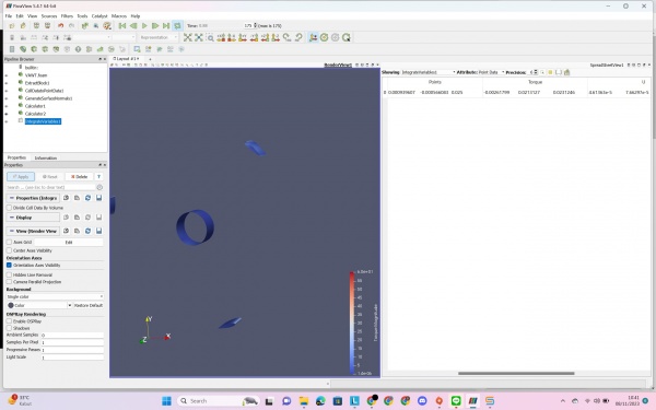
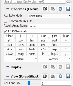
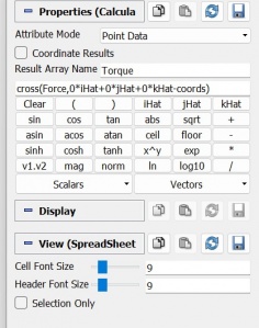
After we simulate the CFD, now we calculate the torque by using some parameter that we can see from the picture. After that we can obtained the result from the simulation
Blade Simulation using CFDSOF
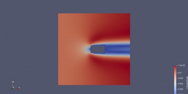
Parameters
Mesh : 10 x 10 x 0.1 Meter
Box : 1 x 3 x 1 Meter
Velocity : 0.01m/s
High pressure area can be seen in the front area of the blade and because the high pressure it can rotate the axis of turbine itself.
One that can be obtained as a result is that because of the obstruction of the blade, the area of the control volume decrease and the velocity of the air should be increase to maintain the same flowrate.
Axial Gas Turbine
https://www.youtube.com/watch?v=spUbnAKy0Fs
Introduction
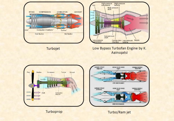
A gas turbine, also called a combustion turbine, is a type of continuous flow internal combustion engine.[1] The main parts common to all gas turbine engines form the power-producing part (known as the gas generator or core) and are, in the direction of flow:
- a rotating gas compressor
- a combustor
- a compressor-driving turbine.
Turbomachinery is widely used equipment in industry such as compressors and turbines in a jet engine; steam turbine in power plants, propeller for ships, hydraulic turbines for irrigation, wind turbines for green energy, small fans for cooling, and so on1. A common feature of these devices is that they all work with fluid and have rotating component. Gorla2 gives a general definition of turbomachinery which says “Turbomachinery is a device in which the energy transfer occurs between a flowing fluid and a rotating element due to dynamic action, and results in a change in pressure and momentum of the fluid”. The usage of turbomachinery has a long history. It is recorded that the waterwheel, a kind of primitive turbomachinery, was invented and used for power generation more than hundred years ago. Although the configuration is simple, it does follow the same basic principle with other complicated modern turbomachinery’s, for instance the compressor and the gas turbine in a jet engine
The gas turbine is an internal combustion (IC) engine that uses air as the working fluid. It is the production of hot gas during fuel combustion, not the fuel itself that the gives gas turbines the name. Gas turbines can utilize a variety of fuels, including natural gas, fuel oils, and synthetic fuels. Combustion occurs continuously in gas turbines, as opposed to reciprocating IC engines, in which combustion occurs intermittently. The engine extracts chemical energy from fuel and converts it to mechanical energy using the gaseous energy of the working fluid (air) to drive the engine and propeller, which, in turn, propel the airplane. The gas turbine engine was first invented in the 1930s∼1940s, which gave the opportunity of rapid development to turbomachinery. From the initial turbojet engine to the modern turbofan engine with large bypass ratio, the evolution of jet engine requires more advanced compressors and turbines with higher stage pressure ratio and higher efficiency
Working Principle
Axial gas turbines are a type of gas turbine where the airflow passes through the turbine in a parallel direction to the axis of rotation. These turbines are commonly used in power generation, aircraft propulsion, and various industrial applications. The working principle of an axial gas turbine involves several steps:
1. Air Intake: The process begins with the intake of ambient air. The air is drawn into the turbine through an inlet and passes through various filtration systems to remove contaminants that could damage the turbine blades.
2. Compression: The incoming air is compressed by a series of axial compressor stages. Each stage consists of a row of rotating blades (rotor) and stationary blades (stator). As the rotor blades spin, they accelerate the air and pass it to the stator blades, which further compress the air by redirecting and slowing it down. This compression process increases the air pressure and temperature.
3. Combustion: The high-pressure, high-temperature compressed air then enters the combustion chamber, where it mixes with fuel (such as natural gas, diesel, or aviation fuel) and undergoes combustion. The burning fuel-air mixture generates extremely high-temperature gases.
4. Expansion (Turbine Stage): The hot and high-pressure gases produced in the combustion chamber flow into the turbine section. The gases expand through a series of turbine stages, each comprising a row of stationary blades and a row of rotating blades. As the gases pass through these stages, the expansion causes the turbine blades to rotate. This rotation is transferred to a shaft connected to the compressor and other machinery.
5. Energy Conversion: The rotating turbine blades transfer the energy of the hot gases into mechanical energy. This mechanical energy is used to drive the compressor at the front end of the turbine and can also be used to power other machinery or generators to produce electricity or propulsion in applications such as aircraft.
6. Exhaust: After the gases have passed through the turbine stages, they exit the turbine at high speed through an exhaust nozzle. In some cases, this exhaust gas may be further utilized for other purposes, such as to generate additional thrust in jet engines or to produce steam for combined-cycle power plants.
The axial gas turbine operates on the principle of converting the energy stored in fuel into mechanical energy through the expansion of high-pressure gases. The continuous flow of air through the various stages of compression, combustion, expansion, and exhaust allows these turbines to efficiently produce power or thrust for different applications.
Comparison
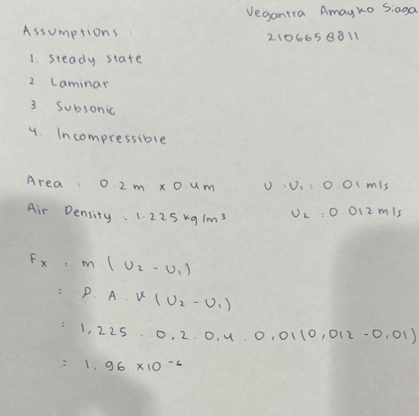
For the calculation, the assumption that we get is :
- Steady-state, laminar, incompressible
- Area of (0.2 * 0.4)m
- Air density of 1.225 kg/m^3
Simulation
From the simulation, the result of the force on a single blade is -1.9632e-6 in the x-axis.
Manual Calculation
From the manual equation, by utilizing the momentum change (shown in the figure above), with the assumption of velocity 2 of 0.012 m/s and velocity 1 of 0.01 m/s and with the flow rate velocity using velocity 1.
The manual calculation yielded a result force of 1.96e-6 N.
Result
- Simulation = -1.9632e-6 N
- Manual = 1.96e-6 N
After the simulation and manual calculation the result that we get is kinda similar but not exact. This is derives by many factor including software error, user limitation, or miss-calculation.
CCIT Visit
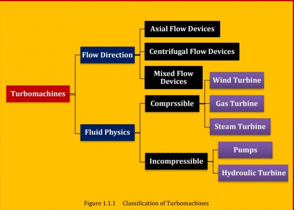
On November 27, 2023, we visited the CCIT lab in Kukusan, Depok. There, we were shown several works produced by Mr. DAI and his colleagues. We were taught about how a turbocharger functions and were able to see its physical form firsthand. Additionally, Bang Edo also taught us about the classification of turbomachinery, which expanded our knowledge.
What is Turbomachinery?
Turbomachinery refers to a class of mechanical devices designed to transfer energy between a rotor and a fluid, typically air or gas, through the use of dynamic principles. These machines are widely used in various industries, including aerospace, power generation, oil and gas, and transportation. Turbomachinery includes devices like turbines, compressors, fans, and pumps, each serving different purposes. Turbines, for instance, extract energy from a fluid flow and convert it into mechanical work, commonly used in power generation or propulsion systems. Conversely, compressors increase the pressure and density of a fluid, essential in processes such as air compression for combustion in engines or gas compression in industrial operations. These machines rely on intricate designs, precise engineering, and a thorough understanding of fluid dynamics to efficiently manipulate fluid flow and energy exchange, making them fundamental components in numerous technological advancements across various sectors.
When is Turbomachinery needed?
Turbomachinery becomes essential in numerous scenarios across diverse industries where the transfer of energy between a rotor and a fluid is pivotal. It finds application in situations requiring the manipulation of fluid flow and the conversion of energy. For instance, in power generation, turbines are indispensable for converting various energy sources, like steam, gas, or water flow, into electrical power. Aerospace heavily relies on turbomachinery for aircraft propulsion systems, utilizing compressors and turbines to create thrust by expelling high-velocity exhaust. In the oil and gas sector, compressors are crucial for moving gases through pipelines or processing facilities. Additionally, turbomachinery plays a role in chemical processes, renewable energy systems, marine propulsion, and even everyday systems like HVAC, where fans and compressors regulate air circulation. Essentially, turbomachinery is needed wherever precise manipulation of fluid dynamics and energy exchange is fundamental to achieve specific industrial or technological objectives.
Why we should use Turbomachinery?
Turbomachinery offers indispensable advantages across numerous industries, primarily due to its ability to efficiently transfer energy between a rotor and a fluid. One of the key reasons for using turbomachinery is its capability to harness various energy sources and convert them into usable forms. For instance, turbines enable the transformation of kinetic or thermal energy from sources like steam, gas, or water into mechanical work or electricity, serving as the backbone of power generation. In the realm of propulsion, turbomachinery, particularly in aerospace, allows for the generation of thrust necessary for aircraft movement by compressing and expelling air at high speeds. Moreover, in industries such as oil and gas, turbomachinery facilitates the movement, compression, and processing of fluids and gases crucial for extraction and transportation. Its efficiency in manipulating fluid flow and energy exchange is pivotal in enhancing productivity, reducing energy losses, and achieving specific performance targets. Overall, the utilization of turbomachinery is driven by its capacity to enable energy conversion, propel technological advancements, and optimize processes in diverse sectors, thereby playing a pivotal role in modern industrial applications.
Who invented the Turbomachinery?
The concept of turbomachinery has evolved over centuries, with contributions from various scientists and engineers across different cultures and time periods. The earliest documented roots of turbomachinery date back to ancient civilizations. For instance, ancient Greek and Roman engineers developed basic water wheels and windmills, which can be considered early forms of turbomachinery for harnessing energy from fluid (water or wind) flow to perform mechanical work However, in terms of more modern turbomachinery, Gustaf de Laval, a Swedish engineer, made significant advancements in the late 19th century. De Laval invented the impulse steam turbine, known as the De Laval turbine, around 1889. This turbine was designed to efficiently convert steam energy into mechanical work by expanding high-pressure steam through nozzles onto a rotor. Another important figure in the history of turbomachinery is Charles Parsons, a British engineer. Parsons developed the reaction steam turbine in the late 19th century, which expanded upon De Laval's design. The Parsons turbine was more practical and widely adopted for power generation and marine propulsion. Parsons' work significantly contributed to the advancement and widespread use of steam turbines in various industries. Since then, numerous engineers, scientists, and inventors worldwide have continued to refine and innovate turbomachinery designs, leading to the development of various types of turbines, compressors, and other devices used in industries such as power generation, aerospace, oil and gas, and more. The evolution and innovation in turbomachinery have been a result of the collaborative efforts and contributions of many individuals over time, with ongoing advancements continuing to shape the field.
How the turbomachinery work?
Turbomachinery operates on the principles of fluid dynamics and energy exchange, utilizing rotating components to transfer energy between a rotor and a fluid, which can be air, gas, or liquid. The functioning of turbomachinery, such as turbines, compressors, pumps, and fans, involves specific mechanisms tailored to their respective purposes. In a turbine, for instance, energy from a fluid—like steam, gas, or water—is directed onto blades or vanes attached to a rotor. As the fluid interacts with these blades, it imparts energy, causing the rotor to spin. This rotational motion is then utilized to perform mechanical work, such as driving a generator to produce electricity in power plants or providing propulsion in aircraft engines. Conversely, compressors work by drawing in a fluid, compressing it, and then expelling it at a higher pressure. The compressor's rotor blades accelerate the fluid, increasing its kinetic energy. As the fluid passes through the compressor, its pressure and density rise, creating a higher-pressure output. The functionality of turbomachinery relies on various principles such as Newton's laws of motion, conservation of mass, conservation of momentum, and thermodynamics. These machines are designed with precision to control fluid flow, maximize energy transfer, and optimize efficiency. Blade profiles, rotor and stator arrangements, and the overall aerodynamic design play crucial roles in achieving desired performance levels. The operation of turbomachinery involves complex interactions between rotating and stationary components, fluid dynamics, and thermodynamic processes. Efficiency improvements often come from advancements in materials, aerodynamics, and computational modeling, allowing for better designs that optimize energy transfer and minimize losses In essence, turbomachinery works by efficiently manipulating fluid flow to transfer energy between the rotor and the fluid, enabling various industrial processes like power generation, propulsion, fluid transportation, and more.
Where the turbomachinery usually used?
Turbomachinery finds widespread application across diverse industries due to its capability to efficiently manipulate fluid flow and transfer energy between a rotor and a fluid. It is commonly used in power generation facilities, including steam and gas turbine power plants, where turbines convert thermal or kinetic energy from steam, gas, or water into electricity. In the aerospace sector, turbomachinery, particularly in jet engines, is crucial for aircraft propulsion, utilizing compressors and turbines to generate thrust by compressing and expelling air at high speeds. Additionally, the oil and gas industry heavily relies on turbomachinery, employing compressors and pumps for gas compression, fluid transportation, and refining processes. Turbomachinery is also integral in chemical and petrochemical plants for fluid handling and processing. Moreover, it plays a vital role in renewable energy systems, such as wind turbines that convert wind energy into electrical power. Other applications include marine propulsion systems, HVAC (Heating, Ventilation, and Air Conditioning) systems, and various manufacturing processes where precise fluid manipulation and energy conversion are essential. Overall, turbomachinery's versatility makes it indispensable across industries where efficient fluid flow control and energy transfer are fundamental for operations and technological advancements.
Pneumatic and Hydraulic
Hydraulic System
A hydraulic system is a technology that utilizes fluids, usually oil or water, to transmit power or energy. It operates through the principles of fluid dynamics and Pascal's law, which states that when pressure is applied to a confined fluid, it is transmitted equally in all directions. In a hydraulic system, this concept is harnessed to generate, control, and transmit power to various mechanical components. It typically consists of a hydraulic pump, which pressurizes the fluid, and a network of hoses, valves, cylinders, and actuators that help in the distribution and utilization of this pressurized fluid to perform tasks. These systems are widely used in various applications, such as heavy machinery, construction equipment, automotive braking systems, and aircraft control systems due to their ability to generate significant force with precise control.
Example of Hydraulic System
Hydraulic systems are widely used in various applications across different industries due to their ability to transmit power efficiently. Here are some common examples:
1. **Heavy Machinery:** Hydraulic systems are extensively employed in heavy equipment like excavators, bulldozers, loaders, and cranes. These machines use hydraulic power to lift heavy loads, manipulate attachments, and perform tasks that require significant force.
2. **Automotive Industry:** Vehicles utilize hydraulic systems in several ways. Hydraulic brakes use fluid pressure to facilitate braking in cars, trucks, and other automobiles. Additionally, power steering systems often rely on hydraulics to assist in steering, making it easier for drivers to maneuver their vehicles.
3. **Aircraft Systems:** Hydraulic systems play a critical role in aircraft for controlling landing gears, wing flaps, and other components. They provide the necessary force and precision to manage these critical functions during flight and while on the ground.
4. **Industrial Machinery:** Manufacturing and industrial machinery frequently use hydraulic systems to operate presses, stamping machines, injection molding machines, and hydraulic presses due to their ability to deliver high force while maintaining control and precision.
5. **Construction Equipment:** Hydraulic systems are integral to construction equipment like cranes, forklifts, backhoes, and hydraulic presses. They power the movement of heavy materials, lifting mechanisms, and the manipulation of attachments required for construction tasks.
6. **Hydraulic Lifts and Elevators:** Elevators in buildings and hydraulic lifts in automotive repair shops or service stations often use hydraulic systems to lift and lower platforms or cars. These systems provide smooth and controlled vertical movement.
7. **Marine Applications:** Ships and boats employ hydraulic systems for steering mechanisms, bow thrusters, and other equipment that requires controlled power transmission in a marine environment.
These examples demonstrate the diverse applications of hydraulic systems across various industries, showcasing their efficiency in transmitting power and facilitating controlled movement or force.
Pneumatic System
A pneumatic system is a technology that utilizes compressed air or inert gases, such as nitrogen, to transmit power and control mechanical motion. Similar to hydraulic systems, pneumatic systems harness the principles of fluid dynamics but use air or gas instead of liquid. These systems consist of a compressor that pressurizes the air or gas, storage containers to store the compressed air, and a network of valves, hoses, cylinders, and actuators to distribute and utilize this compressed air to perform work.
Pneumatic systems are commonly used in various applications due to their simplicity, low cost, and ease of maintenance. They find widespread use in industries such as manufacturing, automotive, and transportation. Examples include pneumatic tools like drills, impact wrenches, and nail guns used in construction and assembly lines. Pneumatic systems are also integral in operating pneumatic actuators for valves in industrial processes, controlling air brakes in vehicles, and powering pneumatic cylinders for linear or rotational motion in various machinery. The ability to generate quick, responsive movement and relatively simple control mechanisms makes pneumatic systems valuable in applications where lightweight, agile, and cost-effective solutions are necessary.
Example of Pneumatic System
Pneumatic Tools: Tools like pneumatic drills, impact wrenches, nail guns, and sanders used in construction, manufacturing, and automotive industries are powered by compressed air. They offer high power-to-weight ratios, making them popular for tasks requiring repetitive or heavy-duty work.
Pneumatic Actuators: Pneumatic actuators, such as cylinders and rotary actuators, are employed in various industrial machines and automation systems. These actuators use compressed air to create linear or rotary motion, performing tasks like opening and closing valves, controlling conveyor belts, or moving components on assembly lines.
Pneumatic Control Systems: Air pressure is often utilized in control systems, such as in air brakes for trucks and buses. These systems use compressed air to control braking mechanisms, providing reliable and responsive braking in large vehicles.
Pneumatic Conveyors: In industries like food processing and manufacturing, pneumatic conveyors use compressed air to transport materials like grains, powders, or granular substances through pipes or tubes from one place to another efficiently.
Pneumatic Suspension Systems: Some vehicles, especially heavy-duty trucks and buses, use pneumatic suspension systems. Compressed air is used to adjust the vehicle's suspension, providing a smoother ride and allowing the vehicle height to be altered for different road conditions.
Dental Tools: In dentistry, pneumatic systems power tools like dental drills, cleaning instruments, and suction devices used by dentists and dental hygienists.
These examples demonstrate the versatility of pneumatic systems across various industries, offering efficient power transmission and control for a wide range of applications.
Step to Build Car Lift
1. The specification needed
2. Designing
3. Calculation
4. Material Selection
5. Safety Factor
6. Calculating the cost
7. Build and testing the model for getting certification
8. Ready for replacement parts and the maintenance
Steam Turbine Experiment
https://www.youtube.com/watch?v=toUOzvxt8HU
Basic Theory
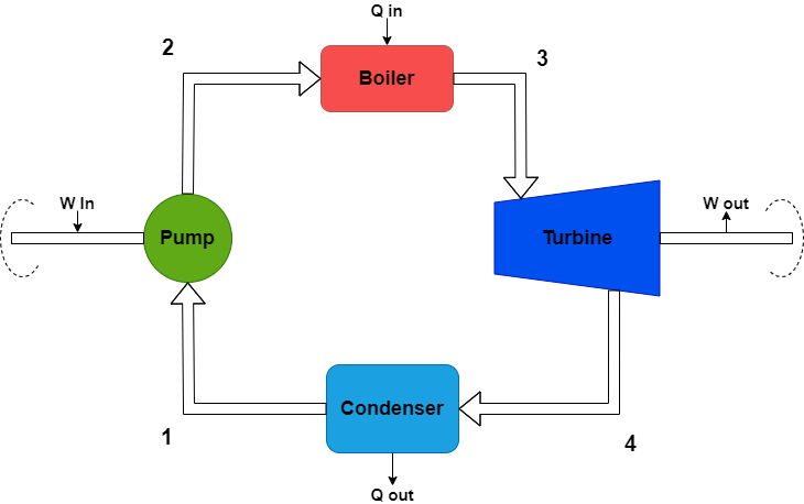
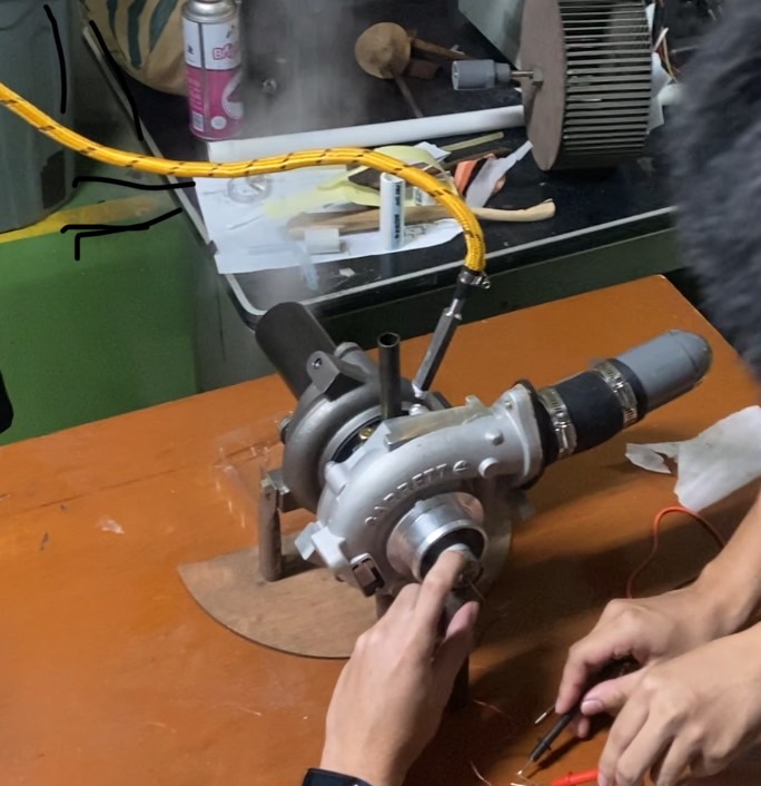
Steam Turbine is the one of the most important competence in ECS. For the final project, Pak DAI give us the instruction to make a steam turbine project that leads by Amato and Bagas. Our Objective is to knowing how steam turbine works with turbocharger component using rankine cycle. The Rankine cycle is a thermodynamic cycle used by steam power plants to generate electricity. It's a theoretical cycle that represents the operation of a steam turbine power system. This cycle forms the basis for most modern steam power plants and provides insights into their operation and efficiency.
Calculation
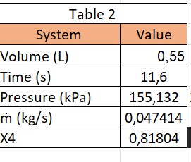
In the experiment, every student have their own number to calculate
- Volume : 0,55 L
- Time : 11,6 s
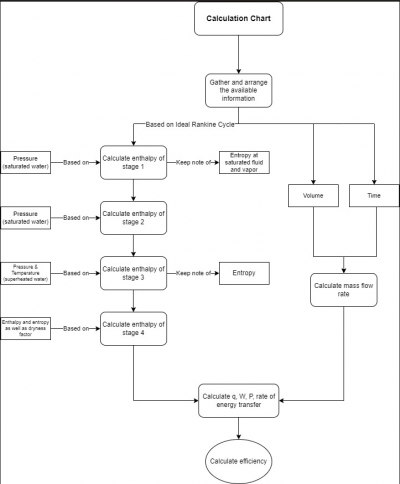
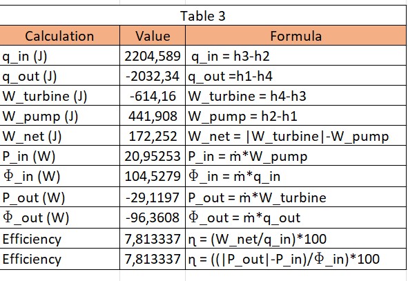
When energy enters the system, it registers as a positive value. Conversely, when the energy exits the system, it also reflects a positive value. To aid in calculating the system's efficiency, spreadsheet is created. This spreadsheet commonly consists of three main tables, structured based on the significance of the variables and parameters at hand.
Here is the diagram used to compute the system's efficiency.
- First table contains the value of enthalpy and entropy.
- Second table contains the value of mass flow rate, volume, and pressure.
- Third table contains the value of work, heat, power, energy, and efficiency
Result
From the calculation we get the results about :
Pin : 20,952 W
Pout : -29,11 W
Efficiency : 7,8%
Conclusion and My Consiousness Effort
The experiment likely demonstrated the basic principles of energy conversion, showcasing how a turbocharger, when repurposed and adapted, can mimic the functionalities of a steam turbine. Through this, participants gained a practical understanding of how energy from steam, in a real-world scenario, can be converted into mechanical work to generate power or drive machinery. The system's efficiency is relatively low, approximately 7.81%. Nevertheless, this figure isn't unfavorable due to the use of basic and minimal tools. Upon obtaining this efficiency result, it becomes evident that our deliberate thoughts significantly influenced this experiment. This experiment may have underscored the importance of efficiency in energy conversion processes. By analyzing the performance of the turbocharger operating as a steam turbine, insights into improving efficiency and maximizing energy output might have been gained, contributing to a broader understanding of optimizing energy systems.
Self Assessment
It was our intention to calculate the efficiency that initiated this experiment. This experiment heightened my awareness and encouraged me to approach daily tasks with deliberate consideration. Throughout the Energy Conversion System classes, I always maintained the belief that I was exerting my utmost effort to learn, study, and grasp the subject matter. However, I acknowledged that this might not have been entirely accurate at times. Hence, there's a need to strive for further improvement in efforts. Furthermore, beyond the aforementioned instance, there remains a necessity for enhancements in the level of exertion and thoughtful analysis to pave the way for a brighter future. Understanding the significance of conscious thinking has underscored the importance of intention. Absent intentional focus, confusion often clouds our decisions regarding what actions are necessary or unnecessary.


