Difference between revisions of "Muhamad Azkhariandra Aryaputra"
(→Axial Steam Turbine) |
(→Youtube Video) |
||
| (70 intermediate revisions by the same user not shown) | |||
| Line 140: | Line 140: | ||
Advantages of steam turbine are simple, reliable, cheap maintenance costs , and steam cleaner from pollution so it can be used for various purposes. | Advantages of steam turbine are simple, reliable, cheap maintenance costs , and steam cleaner from pollution so it can be used for various purposes. | ||
| + | |||
| + | Generally it divided into 2 main types Impulse and Reaction. If static pressure drops occur mainly occur in stationary nozzles with only little or no static pressure drops that occur at the flow through the rotor, the turbine is known as an impulse turbine. In contrast to the reaction turbine, a small percentage of the pressure will fall on the static nozzle and most or the major decrease in pressure will occur in the rotor. | ||
''' Principle''' | ''' Principle''' | ||
| Line 145: | Line 147: | ||
When a gas or vapor travels through a vapor nozzle and is ejected from it at high speeds into the rotor, some of its thermal energy is transformed into kinetic energy when the static pressure decreases. The flow between the blades changes momentum, which causes torque to be produced and the shaft to revolve (as in water turbines). | When a gas or vapor travels through a vapor nozzle and is ejected from it at high speeds into the rotor, some of its thermal energy is transformed into kinetic energy when the static pressure decreases. The flow between the blades changes momentum, which causes torque to be produced and the shaft to revolve (as in water turbines). | ||
| − | [[Screenshot_2023-11-20_003138.png|500px]] | + | [[File:Screenshot_2023-11-20_003138.png|500px]] |
| + | |||
| + | Steam Inlet: | ||
| + | The process begins with the introduction of high-pressure, high-temperature steam into the turbine. This steam is often produced in a boiler by heating water using fossil fuels or other heat sources. | ||
| + | |||
| + | Nozzles: | ||
| + | The high-pressure steam is directed through a series of stationary nozzles. These nozzles serve to accelerate and direct the flow of steam in a controlled manner. | ||
| + | |||
| + | Rotor Blades: | ||
| + | The accelerated steam then impinges on the blades of the turbine rotor. The rotor is a rotating component with a series of blades attached to it. | ||
| + | |||
| + | Rotor Movement: | ||
| + | The impact of high-speed steam on the turbine blades causes the rotor to spin. The rotor is mounted on a shaft, and as it rotates, it transfers its angular momentum to the shaft. | ||
| + | |||
| + | Expansion and Energy Conversion: | ||
| + | As the steam flows over the turbine blades, it undergoes an expansion, and its pressure and temperature decrease. This expansion results in the conversion of the thermal energy of the steam into kinetic energy, causing the rotor to rotate. | ||
| + | |||
| + | Steam Exhaust: | ||
| + | After passing through the turbine blades, the low-pressure steam is exhausted from the turbine. This steam can be further condensed in a condenser, and the condensed water can be returned to the boiler to be heated again, completing the steam cycle. | ||
| + | |||
| + | Multiple Stages: | ||
| + | Axial steam turbines often consist of multiple stages, each with its set of stationary nozzles and rotating blades. The use of multiple stages allows for a more efficient extraction of energy from the steam. | ||
| + | |||
| + | Governor Control: | ||
| + | To maintain a constant speed and control the power output, axial steam turbines are equipped with a governor control system. The governor adjusts the steam flow to the turbine to match the electrical demand. | ||
| + | |||
| + | |||
| + | Steam Turbine Magic Square: | ||
| + | |||
| + | [[File:Screenshot 2023-11-20 003804.png|300px]] | ||
| + | |||
| + | ''' Calculation ''' | ||
| + | |||
| + | The direction of the flow angle is calculated against the direction of the axial flow. Note: in other literature it is often used flow direction according to the relative flow of the blade. | ||
| + | |||
| + | The Euler Equation for the Axial Steam Turbine : E = U(Cx1-Cx2)/g | ||
| + | |||
| + | [[File:Screenshot 2023-11-20 004647.png|200px]] | ||
| + | |||
| + | With the velocity triangle : | ||
| + | |||
| + | [[File:Screenshot 2023-11-20 004913.png|300px]] | ||
| + | |||
| + | |||
| + | ''' Manual Calculation and Simulation Calculation''' | ||
| + | |||
| + | *With assumptions of steady state, laminar, and incompressible flow | ||
| + | *Area of 0.5 m x 0.1 m | ||
| + | *V1= 0.01 m/s and V2= 0.013 m/s | ||
| + | |||
| + | |||
| + | |||
| + | *Simulation: | ||
| + | |||
| + | [[File:Screenshot 2023-11-20 015119.png|300px]] | ||
| + | |||
| + | *Manual Calculation: | ||
| + | |||
| + | [[File:34476.jpg|300px]] | ||
| + | |||
| + | |||
| + | *Analysis | ||
| + | The results of the manual computation are comparable. The simulation's inaccuracies in the drawing might be the reason for the discrepancy between the manual computation and the simulation. | ||
| + | |||
| + | Explanation Video | ||
| + | https://www.youtube.com/watch?v=uvzjOyhon1M&t=15s | ||
| + | |||
| + | === CCIT Visit === | ||
| + | |||
| + | On 27th December 2023 Mr Dai asked ECS 1 class to visit his CCIT lab at Kukusan. Mr Dai asked to show the turbocharger and asked us to study and discuss how the engine works. First we discuss about the turbomachine itself, turbomachine is can be classified into two which are power machine and work machine. Power machine produces energy from fluids, and work machine works other way around which is move the fluid with energy. Power machine also can be classified into two which are reaction and impulse. Reaction power machine needs a change in pressure to work whereas impulse power machine only needs kinetic energy. From this discussion we can classified turbocharger to be the combination of work machine and power machine because it convert fluid into kinetic energy and the kinetic energy can be used for compressor. | ||
| + | |||
| + | From that discussion we can rise questions that can be possibly asked: | ||
| + | * What is the purpose of turbocharger | ||
| + | * What is the basic material of a turbocharger? | ||
| + | * When can the turbocharger no longer be used? | ||
| + | * Where the turbocharger is usually installed? | ||
| + | * Why should we use a turbocharger compared to other tools? | ||
| + | * How to install a turbocharger? | ||
| + | |||
| + | A turbocharger is a device that forces more air into an internal combustion engine's combustion chamber, allowing it to burn more fuel and thus produce more power. The primary purpose of a turbocharger is to increase the efficiency and power output of an engine without significantly increasing its size. The basic materials used in the construction of a turbocharger are typically metals that can withstand high temperatures and mechanical stresses. The main components of a turbocharger include the turbine housing, compressor housing, turbine wheel, compressor wheel, and the shaft that connects the two wheels. | ||
| + | |||
| + | The lifespan of a turbocharger can vary based on factors such as usage, maintenance, and operating conditions. While turbochargers are generally durable components, they can experience wear and eventually fail. The common reasons why a turbocharger might no longer be usable are oil contamination, high temperature, lack of maintenance, etc. Turbochargers are commonly installed in internal combustion engines, both in automotive and non-automotive applications, to improve engine performance. Application of turbochargers are automotive vehicle, marine engine, aircraft engine, ect. | ||
| + | |||
| + | Turbochargers serve as highly efficient tools for enhancing the performance of internal combustion engines. Their primary advantage lies in the significant boost they provide to engine power without the need for larger, heavier engines. By compressing incoming air, turbochargers enable engines to burn more fuel, leading to increased power and torque. This heightened efficiency not only improves overall engine performance but also contributes to enhanced fuel efficiency, a crucial factor in today's automotive landscape. Turbochargers play a pivotal role in meeting strict emission standards by facilitating more complete combustion. Their ability to compensate for reduced air density at higher altitudes ensures consistent engine performance across various environments. Furthermore, turbochargers allow for downsizing of engines, reducing weight and supporting the trend towards more compact, yet powerful, vehicles. This versatility makes turbochargers a preferred choice in automotive, industrial, and other applications. | ||
| + | |||
| + | Installing a turbocharger involves several key steps to ensure proper integration with an internal combustion engine. Begin by identifying a suitable location for the turbocharger, typically along the exhaust and intake paths. Mount the turbine housing in the exhaust system and the compressor housing in the intake system. Connect these housings with a shaft, allowing the turbine, which is driven by exhaust gases, to turn the compressor. Ensure that oil and coolant lines are properly connected to provide lubrication and cooling for the turbocharger. Integrate a wastegate or a variable geometry system to manage boost pressure, preventing over-pressurization. | ||
| + | |||
| + | [[File:38566.jpg|200px]] [[File:38567.jpg|200px]] | ||
| + | |||
| + | === Hydraulic and Pneumatic === | ||
| + | |||
| + | ''' Overview''' | ||
| + | |||
| + | Hydraulic and pneumatic systems are essential components in energy conversion systems, playing distinct roles in various industrial applications. Hydraulic systems utilize incompressible fluids, typically oil, for power transmission, excelling in heavy machinery where precision control and high forces are necessary. They find applications in power generation through hydraulic power plants, converting the energy of flowing water into mechanical power. Meanwhile, pneumatic systems rely on compressed air for energy transmission, offering flexibility and simplicity, making them suitable for applications like robotics and certain manufacturing processes. Both systems contribute to energy storage, with hydraulic systems storing pressurized fluid for release when needed, and pneumatic systems participating in compressed air energy storage. Additionally, these fluid power systems are integral in providing precise control in mechanical systems, with hydraulic actuators in heavy-duty applications and pneumatic systems in scenarios requiring quick and precise movements. Overall, hydraulic and pneumatic systems are indispensable in converting and transmitting energy across a diverse range of industrial contexts. | ||
| + | |||
| + | ''' Principle ''' | ||
| + | |||
| + | Hydraulic and pneumatic systems operate on the fundamental principle of Pascal's law, which asserts that a change in pressure applied to an enclosed fluid is transmitted uniformly in all directions. In hydraulic systems, this principle is applied using an incompressible fluid, typically hydraulic oil, which efficiently transmits force almost instantly throughout the system. Key components include a hydraulic pump, cylinders, and control valves, making hydraulic systems well-suited for heavy machinery and applications requiring high forces and precise control. On the other hand, pneumatic systems utilize a compressible fluid—usually air—allowing for flexibility and adaptability. Compressed air transmits force to various components, such as pneumatic cylinders and control valves, making pneumatic systems ideal for applications demanding rapid and flexible movements, such as in automation and robotics. Despite these differences, both systems rely on the transmission of pressure to convert fluid energy into mechanical work, providing essential solutions in diverse industrial contexts. | ||
| + | |||
| + | == Steam Turbine Report == | ||
| + | |||
| + | === Conscious Thinking === | ||
| + | |||
| + | Conscious thinking is a problem solving method proposed by Mr Dai to solve problems in college. On of the requirement for conscious thinking is to not fear lecturers. There are 4 steps of conscious thinking, the first on is to establish our intention. Intention is something that we are having before we do something. Intention comes from our heart. The second step of conscious thinking is initial thinking about the problem. After we got the intention of what we are going to do we must think about what is the first problem that we are going to have, so we can get solve that problem. The next step is to build the system and study the model. After we know the problem and solve that, then we can build and study the model. After we build and study the model we can go to the last step which is establish step for the solution. Conscious thinking is different from computational thinking because in conscious thinking we must first establish our intention. | ||
| + | |||
| + | === Introduction === | ||
| + | |||
| + | Implementing the conscious thinking method, before we do the report we must think consciously with establish our intension. Our intension is to know and study how the steam turbine work using turbocharger. After that we must know about the initial problem, for example how the steam turbine work? And how to calculate the efficiency of the steam turbine. After that we build the system with the turbocharger and establish solution to calculate the efficiency. | ||
| + | |||
| + | [[File:48518.jpg|300px]] [[File:48519.jpg|200px]] | ||
| + | |||
| + | A turbocharger is a mechanism designed to compel additional air into the combustion chamber of an internal combustion engine. This process enables the engine to burn a greater amount of fuel, resulting in increased power generation. The fundamental objective of a turbocharger is to enhance the efficiency and power yield of an engine without substantially enlarging its dimensions. Commonly, the construction materials for a turbocharger consist of metals capable of enduring elevated temperatures and mechanical pressures. Key components of a turbocharger encompass the turbine housing, compressor housing, turbine wheel, compressor wheel, and the connecting shaft between the two wheels. | ||
| + | |||
| + | === Theory === | ||
| + | The Rankine cycle is a thermodynamic cycle that describes the workings of steam power plants. It is a fundamental concept in engineering and plays a crucial role in the operation of power plants that generate electricity. The basic theory of the Rankine cycle involves the following key processes: | ||
| + | |||
| + | Isentropic Compression (Process 1-2): The working fluid (typically water in steam power plants) is initially in a saturated liquid state. It undergoes isentropic compression in the pump (or feed pump), increasing its pressure. | ||
| + | |||
| + | Isobaric Heat Addition (Process 2-3): The high-pressure liquid is then heated at constant pressure in the boiler or heat exchanger. This results in the liquid becoming a saturated or superheated vapor. | ||
| + | |||
| + | Isentropic Expansion (Process 3-4): The high-pressure, high-temperature vapor expands through the turbine, converting thermal energy into mechanical work. | ||
| + | |||
| + | Isobaric Heat Rejection (Process 4-1): The low-pressure vapor is then condensed back into a liquid in the condenser by rejecting heat to a cooling medium. | ||
| + | |||
| + | [[File:Schematic-of-Rankine-cycle.png|500px]] | ||
| + | |||
| + | The Rankine cycle aims to maximize the conversion of thermal energy into mechanical work. The efficiency of the cycle is determined by the temperature difference between the heat source (in the boiler) and the heat sink (in the condenser). Higher efficiency is achieved by increasing the average temperature of heat addition (in the boiler) and reducing the average temperature of heat rejection (in the condenser). | ||
| + | |||
| + | In practical applications, modifications and enhancements such as reheat, regeneration, and superheating are often employed to improve the efficiency of the Rankine cycle. The Rankine cycle serves as the basis for understanding and designing steam power plants, which are widely used for electricity generation. | ||
| + | |||
| + | === Calculation === | ||
| + | |||
| + | Before the calculation, every student have their specific volume and time for the parameter which are: | ||
| + | |||
| + | * Volume : 0.35 l | ||
| + | * Time : 7.6 s | ||
| + | |||
| + | When energy is introduced into the system, the associated value will be positive. Conversely, when the energy leaves the system, the corresponding value will also be positive. | ||
| + | |||
| + | To facilitate the computation of the system's efficiency, a spreadsheet is generated. Typically, this spreadsheet comprises three primary tables, organized according to the relevance of the available variables and parameters. | ||
| + | |||
| + | This is the flowchart to calculate the efficiency of the system | ||
| + | |||
| + | [[File:Screenshot 2023-12-27 083942.png|400px]] | ||
| + | |||
| + | |||
| + | * First table contains the value of enthalpy and entropy. | ||
| + | [[File:Screenshot 2023-12-27 002852.png|700px]] | ||
| + | |||
| + | * Second table contains the value of mass flow rate, volume, and pressure. | ||
| + | [[File:Screenshot 2023-12-27 003618.png|700px]] | ||
| + | |||
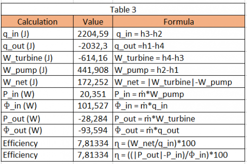
| + | * Third table contains the value of work, heat, power, energy, and efficiency. | ||
| + | [[File:Screenshot 2023-12-27 004039.png|500px]] | ||
| + | |||
| + | === Result === | ||
| + | From the calculation we get the Power which are: | ||
| + | |||
| + | * Pin = 20.351 W | ||
| + | * Pout = 28.28 W | ||
| + | |||
| + | And also we can get the efficiency of the system : | ||
| + | * Efficiency = 7.81% | ||
| + | |||
| + | === Conclusion and Conscious Effort === | ||
| + | |||
| + | The efficiency of this system is low which about 7.81%, but this number is not bad because we use using very simple and minimal tools. After we got the efficiency, we can conclude that our conscious thinking helps us to do this experiment. From we got our intension to calculate the efficiency. This experiment makes me more conscious and inspires me to carry out daily activities with conscious thinking. | ||
| + | |||
| + | === Youtube Video === | ||
| + | |||
| + | https://www.youtube.com/watch?v=bQruv-sUir4 | ||
| + | |||
| + | === Self-assessment === | ||
| + | |||
| + | This semester I learned a lot about energy conversion system. Before the mid test I learned about energy conversion theories. Now we learned about the application of energy conversion in real life like turbocharger in steam turbine. Studying ECS this semester really opened my horizons and opened my mind that learning ECS is not only theory but also learning to see directly with consciousness. Even though I learned a lot, of course my knowledge is still limited and I have to seek more knowledge after this because seeking knowledge must be throughout life, not just at college. If I feel inadequate when studying in class, I have to study more outside of class. When I learn about ECS, I certainly don't forget to stay conscious. Because consciousness is the key to all learning and after learning ECS I feel more conscious in living my daily life and applying ECS lessons. | ||
| + | |||
| + | After studying ECS, I hope that I will be able to apply my knowledge in the world of work when I become an engineer and I also hope that I will remain conscious in running my life and when I become an engineer. | ||
Latest revision as of 09:50, 29 December 2023
Introduction
Name: Muhamad Azkhariandra Aryaputra
NPM: 2106657765
Major: Mechanical Engineering KKI
DoB: 1 January 2003
E-mail: azkha.aryaputra@gmail.com
Hello everyone !
My name is Muhamad Azkhariandra Aryaputra, you can call me Azkha. Right now I'm a Mechanical Engineering student at University of Indonesia and taking Numerical Method class with Pak DAI as the lecturer.
Hydrogen Storage Optimization
Hydrogen storage optimization entails enhancing hydrogen storage technologies' efficiency, capacity, safety, and cost-effectiveness. Because hydrogen has a low energy density, efficient storage is essential for its broad use as an energy carrier. Improving the efficiency, safety, and cost-effectiveness of storing and consuming hydrogen under high-pressure circumstances is referred to as optimizing pressurized hydrogen. Pressurized hydrogen storage is a typical approach for increasing energy density and making hydrogen feasible as an energy carrier.
The objective for this project is to minimize the cost of the material but with good quality and safe material to ensure the optimization of hydrogen storage tank. To achieve this objective there are several constraint that must be considered. The key aspects of the optimization of hydrogen storage are :
Storage Tank Design: Optimizing pressurized hydrogen storage entails creating storage tanks that can bear high pressures safely. The materials used in the tank must be sturdy, lightweight, and resistant to hydrogen embrittlement. To attain the appropriate strength-to-weight ratio, advanced composite materials such as carbon fiber composites are frequently used.
Cost: The cost optimization of hydrogen storage involves finding the most cost-effective solutions for storing hydrogen gas.
Safety Measures: In pressurized hydrogen storage, safety is a vital factor. Implementing safety precautions to prevent leaks, ruptures, or explosions is part of the optimization process. This incorporates pressure release systems, burst discs, and stringent testing and inspection methods to assure the storage tanks' integrity.
Mitigation of Hydrogen Leakage: Minimizing hydrogen leakage is critical for ensuring the safety and efficiency of pressurised hydrogen systems. To reduce leaks, optimization efforts include the use of modern sealing technologies such as metal-to-metal seals or elastomeric seals. Regular maintenance, inspection, and leak detection procedures are also necessary to detect and rectify any potential leaks as soon as possible.
Material Compatibility: Optimizing pressurized hydrogen storage necessitates examining the hydrogen compatibility of storage tank materials. Hydrogen can induce embrittlement or penetration in some materials, resulting in decreased strength or hydrogen loss. To increase the longevity and performance of pressurized hydrogen storage systems, researchers are designing materials that are resistant to hydrogen embrittlement and penetration.
Compressed Hydrogen
The earliest and most essential element in the universe is hydrogen. It has the smallest atomic weight of any element and is made up of a positively charged nucleus proton and a negatively charged electron. Hydrogen is a colorless and odorless gas under typical or ordinary conditions. The most established hydrogen storage technique is compressed hydrogen storage, which includes the physical storage of compressed hydrogen gas in high-pressure tanks. Near-term technology for onboard car hydrogen storage currently consists of 35 and 70 MPa nominal working-pressure compressed gas containers. Compressed hydrogen is often kept in cylinders or high pressure tanks constructed of pressure-resistant materials. The pressure at which hydrogen is compressed varies, although it is often held at pressures ranging from 5,000 to 10,000 pounds per square inch (psi) or more. These high pressures enable more hydrogen to be stored in a given volume. Compressed hydrogen is employed in many different applications, such as fuel cell automobiles, industrial operations, and energy storage systems. It is an essential type of hydrogen storage, particularly for mobile applications, because it allows for relatively small and lightweight storage systems.
Material
The material that is used for this project is Aluminum 6061. Aluminum 6061 is a precipitation-hardened aluminum alloy comprising the principal alloying components magnesium and silicon. It has high mechanical qualities, is weldable, and is widely extruded (second only to 6063 in popularity). It is one of the most prevalent general-purpose aluminum alloys. The aluminum alloy 6061 is a significant raw material for aluminum liner carbon fiber full-wrapped composite gas cylinders, the hydrogen compatibility of which impacts the safety and dependability of gas cylinders to a large extent. Aluminum 6061 is chosen because the relative cost of this material is not too expensive but very suitable for the pressurized hydrogen tank material.
Design
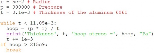
The optimization of the design is for making the hydrogen tank for the minimal cost, so the calculation for the diameter and the height of the tank is presented below
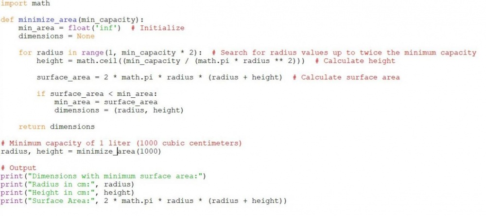
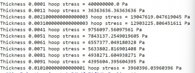
The thickness of the tank
From the result above the estimation of the thickness of the tank is around 6 mm. The cost for the 6 mm Aluminum 6061 is Rp130.000 (240 cm^2). The total area of the tank that have been calculated is 565 cm^2. Therefore for the total cost is 565/240 x Rp130.000 = Rp306.000
Conclusion
We know from the explanation above the constraints for this hydrogen tank optimization project is the cost and the design. The design that is used for this project is cylindrical shape tank with the diameter 10 cm and the height of 13 cm. These diameter and height is calculated because we want to minimize the cost but with the wanted volume. From that design the material that used for this project is Aluminum 6061 and therefore we got the cost for the project is Rp306.000.
ECS 1 Class
ECS 1 First Meeting
Einstein quotes about education : What is left after you’re forgotten all you have learned. Mr Dai said what if you all forgot about calculus. What is the purpose of calculus? I think calculus is not just about solving differentials, derivatives or others. Calculus is used for us to solve everyday problems because it makes us think critically. Energy conversion system is a very wide subject so students must not focus on just the equation, but why we used that equation to solve the energy conversion system problem.
Energy has a key word which is efficiency. We must count every energy that is useful for us because all that energy must be calculated to know how efficient that energy is. In my opinion energy is the source of life because humans need energy to live in this world. There are several laws of energy and one of them is that energy can be converted to another form of energy.
There are three principles of logic, the first one is law of identity, the second one id law of no contradiction, and the third one is aw of the middle excluded.
CFD Simulation
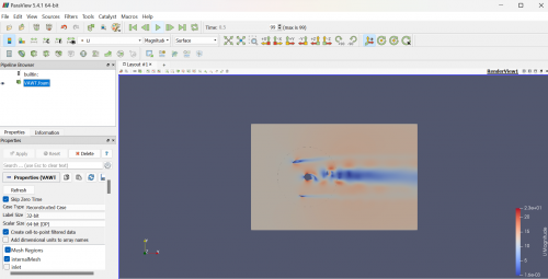
CFC simulation of Vertical Axis Wind Turbine with initial condition of:
- Start Time = 0
- End Time = 0.5
- Inlet Velocity = (12 0 0)
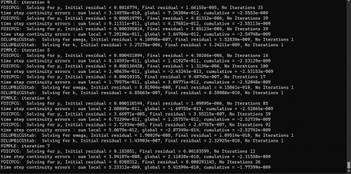
By using command prompt
and visualize it with Paraview
This is the simulation of VAWT blade speed with paraview at the time of 0.5 s
ECS Second Week
In this week we learnt about the calculation of the torsion of the VAWT by using Paraview
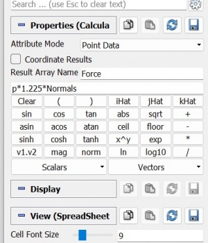
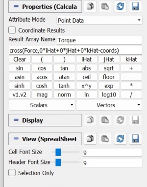
Using the calculator feature to calculate the torque
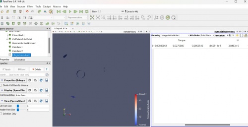
And we can got the result
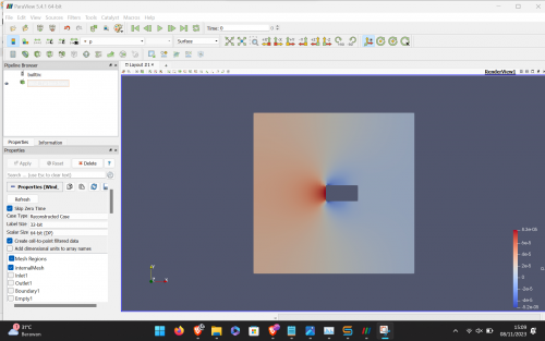
We also calculated the pressure of single blade in a simulation with the dimension of 1 x 3 x 1 meter with base mesh of 10 x 10 x 0.1 meter with velocity of 0.01 m/s
The figure shows a high-pressure area at the front of a blade, which can contribute to the turbine's rotation. Theoretically, a larger blade surface area results in higher pressure, but it also increases weight due to the additional material required.
We also can calculate the velocity
Axial Steam Turbine
Overview
The purpose of steam turbines is to transform the thermal energy contained in steam into mechanical energy. Thermal power plants employ them to generate energy. The electric generator is powered by the steam that is directed via the turbine and onto several revolving blades. These power stations run on nuclear, coal, natural gas, or other fossil fuels.
A steam turbine is a heat engine that achieves a closed state to the optimal reversible expansion process by employing numerous stages to get most of its development in thermodynamic efficiency.
Advantages of steam turbine are simple, reliable, cheap maintenance costs , and steam cleaner from pollution so it can be used for various purposes.
Generally it divided into 2 main types Impulse and Reaction. If static pressure drops occur mainly occur in stationary nozzles with only little or no static pressure drops that occur at the flow through the rotor, the turbine is known as an impulse turbine. In contrast to the reaction turbine, a small percentage of the pressure will fall on the static nozzle and most or the major decrease in pressure will occur in the rotor.
Principle
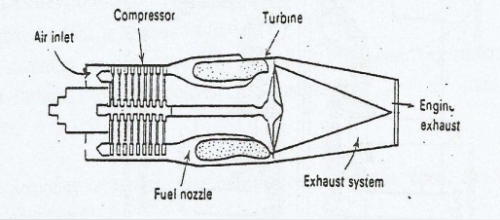
When a gas or vapor travels through a vapor nozzle and is ejected from it at high speeds into the rotor, some of its thermal energy is transformed into kinetic energy when the static pressure decreases. The flow between the blades changes momentum, which causes torque to be produced and the shaft to revolve (as in water turbines).
Steam Inlet: The process begins with the introduction of high-pressure, high-temperature steam into the turbine. This steam is often produced in a boiler by heating water using fossil fuels or other heat sources.
Nozzles: The high-pressure steam is directed through a series of stationary nozzles. These nozzles serve to accelerate and direct the flow of steam in a controlled manner.
Rotor Blades: The accelerated steam then impinges on the blades of the turbine rotor. The rotor is a rotating component with a series of blades attached to it.
Rotor Movement: The impact of high-speed steam on the turbine blades causes the rotor to spin. The rotor is mounted on a shaft, and as it rotates, it transfers its angular momentum to the shaft.
Expansion and Energy Conversion: As the steam flows over the turbine blades, it undergoes an expansion, and its pressure and temperature decrease. This expansion results in the conversion of the thermal energy of the steam into kinetic energy, causing the rotor to rotate.
Steam Exhaust: After passing through the turbine blades, the low-pressure steam is exhausted from the turbine. This steam can be further condensed in a condenser, and the condensed water can be returned to the boiler to be heated again, completing the steam cycle.
Multiple Stages: Axial steam turbines often consist of multiple stages, each with its set of stationary nozzles and rotating blades. The use of multiple stages allows for a more efficient extraction of energy from the steam.
Governor Control: To maintain a constant speed and control the power output, axial steam turbines are equipped with a governor control system. The governor adjusts the steam flow to the turbine to match the electrical demand.
Steam Turbine Magic Square:
Calculation
The direction of the flow angle is calculated against the direction of the axial flow. Note: in other literature it is often used flow direction according to the relative flow of the blade.
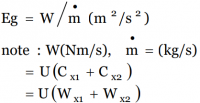
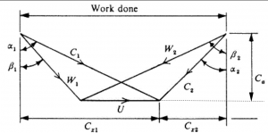
The Euler Equation for the Axial Steam Turbine : E = U(Cx1-Cx2)/g
With the velocity triangle :
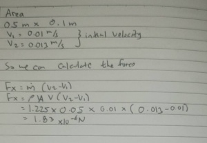
Manual Calculation and Simulation Calculation
- With assumptions of steady state, laminar, and incompressible flow
- Area of 0.5 m x 0.1 m
- V1= 0.01 m/s and V2= 0.013 m/s
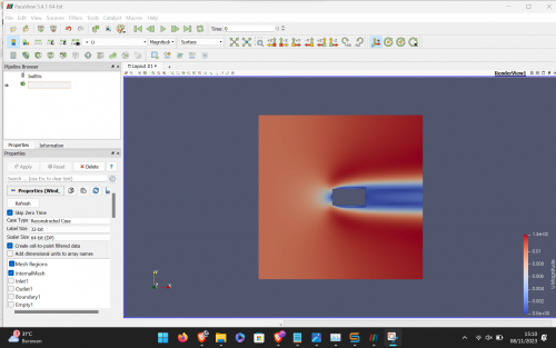
- Simulation:
- Manual Calculation:
- Analysis
The results of the manual computation are comparable. The simulation's inaccuracies in the drawing might be the reason for the discrepancy between the manual computation and the simulation.
Explanation Video https://www.youtube.com/watch?v=uvzjOyhon1M&t=15s
CCIT Visit
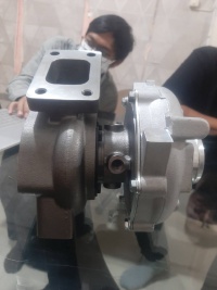
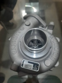
On 27th December 2023 Mr Dai asked ECS 1 class to visit his CCIT lab at Kukusan. Mr Dai asked to show the turbocharger and asked us to study and discuss how the engine works. First we discuss about the turbomachine itself, turbomachine is can be classified into two which are power machine and work machine. Power machine produces energy from fluids, and work machine works other way around which is move the fluid with energy. Power machine also can be classified into two which are reaction and impulse. Reaction power machine needs a change in pressure to work whereas impulse power machine only needs kinetic energy. From this discussion we can classified turbocharger to be the combination of work machine and power machine because it convert fluid into kinetic energy and the kinetic energy can be used for compressor.
From that discussion we can rise questions that can be possibly asked:
- What is the purpose of turbocharger
- What is the basic material of a turbocharger?
- When can the turbocharger no longer be used?
- Where the turbocharger is usually installed?
- Why should we use a turbocharger compared to other tools?
- How to install a turbocharger?
A turbocharger is a device that forces more air into an internal combustion engine's combustion chamber, allowing it to burn more fuel and thus produce more power. The primary purpose of a turbocharger is to increase the efficiency and power output of an engine without significantly increasing its size. The basic materials used in the construction of a turbocharger are typically metals that can withstand high temperatures and mechanical stresses. The main components of a turbocharger include the turbine housing, compressor housing, turbine wheel, compressor wheel, and the shaft that connects the two wheels.
The lifespan of a turbocharger can vary based on factors such as usage, maintenance, and operating conditions. While turbochargers are generally durable components, they can experience wear and eventually fail. The common reasons why a turbocharger might no longer be usable are oil contamination, high temperature, lack of maintenance, etc. Turbochargers are commonly installed in internal combustion engines, both in automotive and non-automotive applications, to improve engine performance. Application of turbochargers are automotive vehicle, marine engine, aircraft engine, ect.
Turbochargers serve as highly efficient tools for enhancing the performance of internal combustion engines. Their primary advantage lies in the significant boost they provide to engine power without the need for larger, heavier engines. By compressing incoming air, turbochargers enable engines to burn more fuel, leading to increased power and torque. This heightened efficiency not only improves overall engine performance but also contributes to enhanced fuel efficiency, a crucial factor in today's automotive landscape. Turbochargers play a pivotal role in meeting strict emission standards by facilitating more complete combustion. Their ability to compensate for reduced air density at higher altitudes ensures consistent engine performance across various environments. Furthermore, turbochargers allow for downsizing of engines, reducing weight and supporting the trend towards more compact, yet powerful, vehicles. This versatility makes turbochargers a preferred choice in automotive, industrial, and other applications.
Installing a turbocharger involves several key steps to ensure proper integration with an internal combustion engine. Begin by identifying a suitable location for the turbocharger, typically along the exhaust and intake paths. Mount the turbine housing in the exhaust system and the compressor housing in the intake system. Connect these housings with a shaft, allowing the turbine, which is driven by exhaust gases, to turn the compressor. Ensure that oil and coolant lines are properly connected to provide lubrication and cooling for the turbocharger. Integrate a wastegate or a variable geometry system to manage boost pressure, preventing over-pressurization.
Hydraulic and Pneumatic
Overview
Hydraulic and pneumatic systems are essential components in energy conversion systems, playing distinct roles in various industrial applications. Hydraulic systems utilize incompressible fluids, typically oil, for power transmission, excelling in heavy machinery where precision control and high forces are necessary. They find applications in power generation through hydraulic power plants, converting the energy of flowing water into mechanical power. Meanwhile, pneumatic systems rely on compressed air for energy transmission, offering flexibility and simplicity, making them suitable for applications like robotics and certain manufacturing processes. Both systems contribute to energy storage, with hydraulic systems storing pressurized fluid for release when needed, and pneumatic systems participating in compressed air energy storage. Additionally, these fluid power systems are integral in providing precise control in mechanical systems, with hydraulic actuators in heavy-duty applications and pneumatic systems in scenarios requiring quick and precise movements. Overall, hydraulic and pneumatic systems are indispensable in converting and transmitting energy across a diverse range of industrial contexts.
Principle
Hydraulic and pneumatic systems operate on the fundamental principle of Pascal's law, which asserts that a change in pressure applied to an enclosed fluid is transmitted uniformly in all directions. In hydraulic systems, this principle is applied using an incompressible fluid, typically hydraulic oil, which efficiently transmits force almost instantly throughout the system. Key components include a hydraulic pump, cylinders, and control valves, making hydraulic systems well-suited for heavy machinery and applications requiring high forces and precise control. On the other hand, pneumatic systems utilize a compressible fluid—usually air—allowing for flexibility and adaptability. Compressed air transmits force to various components, such as pneumatic cylinders and control valves, making pneumatic systems ideal for applications demanding rapid and flexible movements, such as in automation and robotics. Despite these differences, both systems rely on the transmission of pressure to convert fluid energy into mechanical work, providing essential solutions in diverse industrial contexts.
Steam Turbine Report
Conscious Thinking
Conscious thinking is a problem solving method proposed by Mr Dai to solve problems in college. On of the requirement for conscious thinking is to not fear lecturers. There are 4 steps of conscious thinking, the first on is to establish our intention. Intention is something that we are having before we do something. Intention comes from our heart. The second step of conscious thinking is initial thinking about the problem. After we got the intention of what we are going to do we must think about what is the first problem that we are going to have, so we can get solve that problem. The next step is to build the system and study the model. After we know the problem and solve that, then we can build and study the model. After we build and study the model we can go to the last step which is establish step for the solution. Conscious thinking is different from computational thinking because in conscious thinking we must first establish our intention.
Introduction
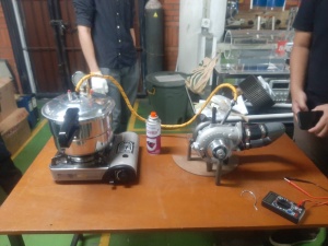
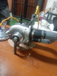
Implementing the conscious thinking method, before we do the report we must think consciously with establish our intension. Our intension is to know and study how the steam turbine work using turbocharger. After that we must know about the initial problem, for example how the steam turbine work? And how to calculate the efficiency of the steam turbine. After that we build the system with the turbocharger and establish solution to calculate the efficiency.
A turbocharger is a mechanism designed to compel additional air into the combustion chamber of an internal combustion engine. This process enables the engine to burn a greater amount of fuel, resulting in increased power generation. The fundamental objective of a turbocharger is to enhance the efficiency and power yield of an engine without substantially enlarging its dimensions. Commonly, the construction materials for a turbocharger consist of metals capable of enduring elevated temperatures and mechanical pressures. Key components of a turbocharger encompass the turbine housing, compressor housing, turbine wheel, compressor wheel, and the connecting shaft between the two wheels.
Theory
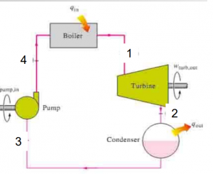
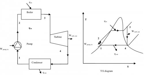
The Rankine cycle is a thermodynamic cycle that describes the workings of steam power plants. It is a fundamental concept in engineering and plays a crucial role in the operation of power plants that generate electricity. The basic theory of the Rankine cycle involves the following key processes:
Isentropic Compression (Process 1-2): The working fluid (typically water in steam power plants) is initially in a saturated liquid state. It undergoes isentropic compression in the pump (or feed pump), increasing its pressure.
Isobaric Heat Addition (Process 2-3): The high-pressure liquid is then heated at constant pressure in the boiler or heat exchanger. This results in the liquid becoming a saturated or superheated vapor.
Isentropic Expansion (Process 3-4): The high-pressure, high-temperature vapor expands through the turbine, converting thermal energy into mechanical work.
Isobaric Heat Rejection (Process 4-1): The low-pressure vapor is then condensed back into a liquid in the condenser by rejecting heat to a cooling medium.
The Rankine cycle aims to maximize the conversion of thermal energy into mechanical work. The efficiency of the cycle is determined by the temperature difference between the heat source (in the boiler) and the heat sink (in the condenser). Higher efficiency is achieved by increasing the average temperature of heat addition (in the boiler) and reducing the average temperature of heat rejection (in the condenser).
In practical applications, modifications and enhancements such as reheat, regeneration, and superheating are often employed to improve the efficiency of the Rankine cycle. The Rankine cycle serves as the basis for understanding and designing steam power plants, which are widely used for electricity generation.
Calculation
Before the calculation, every student have their specific volume and time for the parameter which are:
- Volume : 0.35 l
- Time : 7.6 s
When energy is introduced into the system, the associated value will be positive. Conversely, when the energy leaves the system, the corresponding value will also be positive.
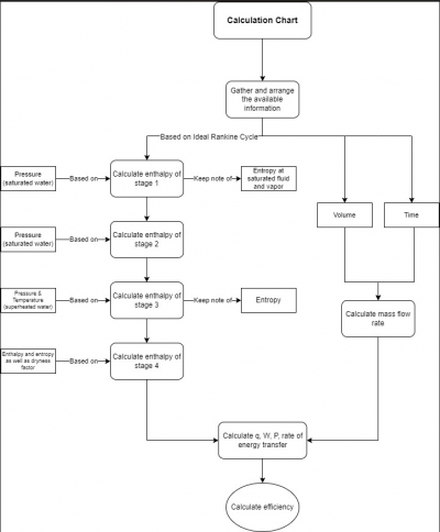
To facilitate the computation of the system's efficiency, a spreadsheet is generated. Typically, this spreadsheet comprises three primary tables, organized according to the relevance of the available variables and parameters.
This is the flowchart to calculate the efficiency of the system
- First table contains the value of enthalpy and entropy.
- Second table contains the value of mass flow rate, volume, and pressure.
- Third table contains the value of work, heat, power, energy, and efficiency.
Result
From the calculation we get the Power which are:
- Pin = 20.351 W
- Pout = 28.28 W
And also we can get the efficiency of the system :
- Efficiency = 7.81%
Conclusion and Conscious Effort
The efficiency of this system is low which about 7.81%, but this number is not bad because we use using very simple and minimal tools. After we got the efficiency, we can conclude that our conscious thinking helps us to do this experiment. From we got our intension to calculate the efficiency. This experiment makes me more conscious and inspires me to carry out daily activities with conscious thinking.
Youtube Video
https://www.youtube.com/watch?v=bQruv-sUir4
Self-assessment
This semester I learned a lot about energy conversion system. Before the mid test I learned about energy conversion theories. Now we learned about the application of energy conversion in real life like turbocharger in steam turbine. Studying ECS this semester really opened my horizons and opened my mind that learning ECS is not only theory but also learning to see directly with consciousness. Even though I learned a lot, of course my knowledge is still limited and I have to seek more knowledge after this because seeking knowledge must be throughout life, not just at college. If I feel inadequate when studying in class, I have to study more outside of class. When I learn about ECS, I certainly don't forget to stay conscious. Because consciousness is the key to all learning and after learning ECS I feel more conscious in living my daily life and applying ECS lessons.
After studying ECS, I hope that I will be able to apply my knowledge in the world of work when I become an engineer and I also hope that I will remain conscious in running my life and when I become an engineer.


