Nathan Abraham Primana
Contents
- 1 Energy Conversion System 02 ENME615022
- 2 Daily Class Posts
- 3 VIDEO PRESENTATIONS/UPDATE INDIVIDUAL ASSIGNMENT
- 4 PERSONAL PROJECT: "INTERNAL COMBUSTION ENGINE WITH PARAMETERS OF HYDROLYSIS"
- 5 Quiz Energy Conversion System 2
- 6 PERSONAL PROJECT: Hydrolisis Experiment for IC Engine Experimenation in OpenModellica
- 7 FINAL PROJECT: Hydrolisis Experiment for torch and temperature rise
Energy Conversion System 02 ENME615022
Hi, allow me to introduce myself, my name is Nathan Abraham Primana, and I partake in the class of Energy Conversion System 2 of class ENME615022. In this page, I will give the following updates on my Energy Conversion System 2 assignments and class.
My Biodata:
Name : Nathan Abraham Primana
NPM : 2006517833
Major : Mechanical Engineering
Daily Class Posts
Energy Conversion System 2 – Date: 14 February 2023 – Topic: Energy Consumption and Production.
As for today’s class of ECS 2, I was listening to the lecture that was brought by Prof Adi;
leading crisis in energy consumption and production:
1. energy outlook 2023-2024, although it wouldn’t make a significant change towards the climate significantly, what would be the outcome in the long run.
2. how can we reduce carbon emissions?
a. where does the vast majority of carbon emission produce by?
3. would a clean earth be achievable at a time where most people are dependant towards oil and gas a source of energy to run vehicles and for electricity?
4. does electric vehicle really reduce the number of pollutants towards the atmosphere?
a. what is involved in the production of electric vehicle components and parts?
b. corelating question back: what actions would be needed in order to reduce large amounts of air pollutants from the atmosphere?
Energy Conversion System 2 – Date: 21 February 2023 – Topic: Correlations in Industries of engineering and Energy production.
On th 21st of February 2023, we were asked to find the relation of the engineering industries such as sugar cane, battery, oil and gas with the help of the opensource Artificial Intelligence (AI).
To which I got the response:
The engineering industries you mentioned (sugar cane, battery, oil, and gas) are related in the sense that they are all involved in the production, extraction, and refining of natural resources to create products that are used in our daily lives.
Sugar cane engineering involves the cultivation, processing, and refinement of sugar cane to produce sugar, which is used as a sweetener in food and beverages.
Battery engineering involves the design and manufacturing of batteries, which are used to store electrical energy for various applications, such as powering electronic devices, electric vehicles, and renewable energy systems.
Oil engineering involves the exploration, extraction, transportation, and refining of crude oil to produce various products, such as gasoline, diesel, and jet fuel, as well as other petrochemicals used in manufacturing. Gas engineering involves the exploration, extraction, transportation, and refining of natural gas to produce products such as fuel for heating and cooking, as well as industrial and commercial uses. Overall, these industries are related in that they are all involved in the production and refinement of natural resources to create products that are important for modern society. about the engineering industry of Oil and gas towards the rivalry in the rise of electric vehicles and renewable energy.
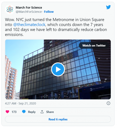
To then I followed up the question by asking ChatGPT about the vast majority of carbon emission and it responded with: The vast majority of carbon emissions are produced by burning fossil fuels such as coal, oil, and natural gas for energy production. This includes emissions from power plants, transportation, industry, and residential and commercial buildings. Other human activities, such as deforestation and agriculture, also contribute to carbon emissions. Carbon emissions contribute to climate change, which can have significant impacts on the environment and human health. As a result, there is a growing effort to reduce carbon emissions by transitioning to cleaner energy sources, improving energy efficiency, and adopting more sustainable practices. This then got me thinking as to what it would take to create a cleaner environment and would it actually be achievable in the near future. This came about when I visited New York a couple of years ago and saw the timer or countdown on one of the LED screens stating the time left for us to make a change in carbon emission. This climate clock led by a climate change organization to achieve focus among people to realize the point of which carbons are present as pollution in the environment and has impacted the climate, forcing us to make a change in energy consumptions and productions, how would we be able to do that?
source: https://www.globalcitizen.org/en/content/new-york-clock-countdown-climate-disaster/
Then leads to the question that I thought about again, would electrical vehicles really reduce the amount of carbon emission in the earth, as we speak, thousands upon millions of carbons are released to the air in the form of pollution from factories of electric vehicles to produce components such as batteries, they require element from the earth, commonly Nickel and Lithium.
(Will be diving into that soon)
How would globalization then impact the fair trade in battery production?
Energy Conversion System 2 – Date: 28 February 2023 – Topic: ENERGY COMBUSTION IN FORM OF ENERGY CONVERSION SYSTEM.
With what Pak DAI had given in the whiteboard, I wrote down the equation to;
This shows that the derivative of energy with respect to time is equal to the heat energy added with work.
What are the difference with these IC engine: Cars, motorbikes, generator, etc.
types of fuel are different.
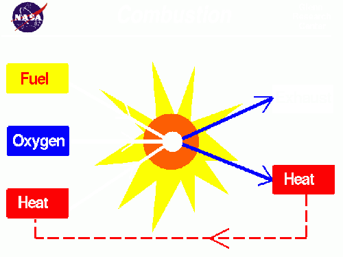
Combustion occurs when there is a mixture with fuel and air inside of a chamber i.e. an engine.
what happens during an internal combustion ->
thus what is combustion? -> the process of burning something.
From chemical prespective: rapid chemical combination of a substance with oxygen, involving the production of heat and light.
Pyrolysis:
Energy Conversion System 2 – Date: 7 March 2023 – Topic: DESALINATION PROCESS AND THE CORELATION WITH GRAPHENE AS A USEFUL MATERIAL IN WATER TREATMENT.
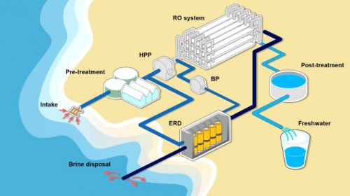
Desalination is the process in which removes salt and other forms of minerals from the water collected in the sea or usually brackish water, this ensures in making it suitable for human consumption, agriculture or even industrial use. Desalination can be achieved with the methods listed below, most common are: Reverse osmosis (RO): process that involves forcing out water through a semi-permeable membrane allowing only the water molecules to pass through, this blocks the salt and other impurities inside the salt water.
Distillation: Conventional process that involves heating the water up to its boiling temperature and collecting the steam while condensing it back, thus creating a clean water that leaves the salt and impurities in needed behind.
Electrodialysis: Process of using electric current to remove salt and other impurities from the water by passing it through a series of membranes of charges electrodes.
Desalination: become a popular method of obtaining fresh water for areas that are distant from clean water access. On the other hand, the use of desalination is a big energy consumptive process requiring a vast infrastructure that can also be cost efficient, thus leading to economical values and consumptive. Furthermore, the by-products of the desalination process, brine, has a negative environmental impact on the environment if it is not properly disposed. Despite the challenges faced, desalination has become a critical component of water management strategies in rural areas that can’t have access to clean running water and around the world.
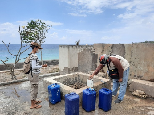
With an example that desalination is used in the Island of Bali, it is used in all sorts of aspects such as FnB businesses, hotel accommodations, rural areas, villages, etc. This is due to the fact that Bali faces major water shortages from the amount of tourism that has brought in amounts of foreigners to the island, brought up the problem of water sufficiency. (https://kopernik.info/en/current-projects/waste-for-water-creating-a-communityled-water-desalination-business-to-provide-clean-drinking-water)
With the rise in water desalination processes, membranes for water purification and desalination are used more to solve the global challenge facing of pollution and water scarcity. It requires a high selective and high permiable membrane available to adresss the limitation of current membrane technologies, this is where graphene was observed.
Graphene composed of carbone atoms that are bonded through hexagonal patterns, mono and double layered graphene are aligned in a thin formation that can be considered a two-dimensional material. The honeycomb pattern ensures that it is strong, light and most conductive. The single layer of carbon atoms would provide as a basis for many other materials. Graphene oxide (GO) is what the disperse of basic solutions to produce GO, it is a single atomic layer of graphene with oxidized functional groups of structure.
On the graphene based desalination membrane technology, is great in water desalination as it is cheap due to its light weight properties from the honeycomb structure. Some challenges are faced such that the production process are expensive and consumptive, furthermore, with its usage in more and more fields, hoping that the cost of production would be reduced and be a future problem that need a solution to.
Energy Conversion System 2 – Date: 10 March 2023 – Topic:CCIT WORKSHOP.
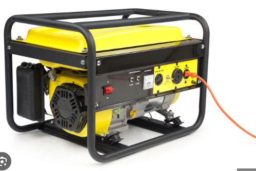
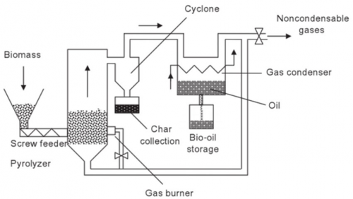
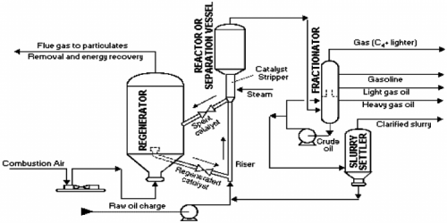
With the class invited to visit the CCIT workshop, the introduction of the IC engine used and Pyrolisis as a form of discussion and bring up to understand deeper and further regarding the individual assignment projects and the MRPP or what is known as the Mobile Refinery and Power Plant. The three equipments in the MRPP is the generator, pyrolysis and the FCC or the Fluid Catalytic Cracking. Steps:
1. Generator – A generator is a machine that converts mechanical energy into electrical energy. It is also known as an alternator, because it generates alternating current (AC) electricity. Generators can be powered by a variety of sources, such as combustion engines, turbines, and water or wind power. The mechanical energy is typically transferred to the generator through a shaft, belt, or chain. The Generator is powered by the LPG gas tank. The generator produces 5000 watts of electricity and flue gasses.
2. Pyrolysis - is a chemical process that involves the thermal decomposition of organic materials in the absence of oxygen or with limited amounts of oxygen. The organic material is heated to high temperatures, causing it to break down into smaller molecules. The process can be used to convert a variety of organic materials, including biomass, waste plastics, and rubber, into useful products such as biofuels, chemicals, and carbon black. There are 2 types of pyrolysis carrying out processes, such that they are low pyrolysis, fast pyrolysis, and flash pyrolysis, depending on the temperature, heating rate, and reaction time. Slow pyrolysis involves heating the material at low temperatures (around 400-600°C) for several hours, while fast and flash pyrolysis involve heating the material at high temperatures (around 400-800°C) for a shorter period of time.
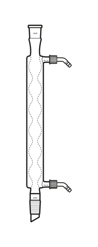
3. Condenser – condensation is a process of cooling down a steam or gasses due to the increasing temperatures of the gasses from the flue gasses on the previous step of the generator, the gasses then flowed up to the pyrolysis tank to then be condensed, the condenser is used to separate the crude bio oil from the gas, repeated the step of condensation throughout a total of four times to then ensure that final form of the crude bio oil is collected.
4. Fluid Catalytic Cracking (FCC) - process used in petroleum refineries to convert high-boiling-point, high-molecular-weight hydrocarbons into smaller, lighter molecules. This process is used to produce gasoline, diesel, and other valuable products from crude oil. The products of FCC include gasoline, diesel, and other hydrocarbons that are used as feedstocks for other refining processes. The process is very important for the production of gasoline, as it can produce high-octane gasoline with a lower sulphur content than other refining methods.
VIDEO PRESENTATIONS/UPDATE INDIVIDUAL ASSIGNMENT
1st Video Presentation: https://youtu.be/gVHkSi-xOKU
2nd Video Progress Update: https://youtu.be/1tmqeaNwEZg
PERSONAL PROJECT: "INTERNAL COMBUSTION ENGINE WITH PARAMETERS OF HYDROLYSIS"
Introduction
With the personal project that we each must carry out on our Energy Conversion System 02 class, the topic that i am choosing for my Project is an IC Engine or Internal Combustion Engine.
Further more, the use of OpenModellica software is the used in order to achieve testing models, run simulation times and results.
Background
IC engine is what had caught my idea on this personal project of mine for my ECS 02 class, this is because we are at a state of transition from a combustion engine to run transportations and vehicles to electric modes of transport such as electric cars and motorbikes. Example of the use of electrical vehicles that are already in Indonesia is the electric motorcycle used by gojek drivers.
 Source: https://dailysocial.id/post/gojek-pours-investment-to-gogoro-through-pipe-ready-for-electric-motorcycle-trial
Another example of implementations of electric vehicles slowly making a move in Indonesian roads are the Wuling AirEV roaming around the streets with a range of different variations in distance travel.
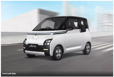 Source: https://www.oto.com/en/mobil-baru/wuling/ev/gambar
Leading Questions
1. What would be the environmental difference in both IC engine to EV when the production of EV also would still pollute the envionment?
2. How efficient is the use of an ideal IC engine compared to that of an EV in terms of top speed, capability and torque with the results taken from Openmodellica and a real test?
Methods and Procedure
Using the Software OpenModellica to use in calculating the efficiency given from the use of a Internal Combustion Engine then given that compared to a Electrical Vehicle with the use of external softwares, further calculations and research are still on going.
With the use of thermosysPro libraries in OpenModellica is the necessar to get the viable data and results from the test model used based on a real hands-on IC Engine that I have at the moment, then can compare the efficiency of the power that is produced to the power or energy released.
A test with a bench test is necessary followed by the use in fuel usage and range test safely, while the vehicle is in use.
Additional Theory
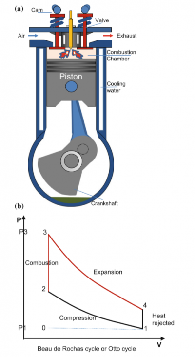
From the book of ThermosysPro, I found that there is a diagram of a piston inside an IC Engine and also there is a otto cycle graph which explains about the Combustion process happening inside of the IC Engine or in this case the difference in pressure to volume of the piston.
a.) Diagram of IC Engine
b.) Otto cycle in Pressure to Volume Diagram
• Process 2–3: constant volume heat addition (instant combustion);
• Process 3–4: isentropic expansion of the products of combustion;
• Process 4–1: constant volume cooling (heat rejection);
• Process 1–0: exhaust of the flue gases.
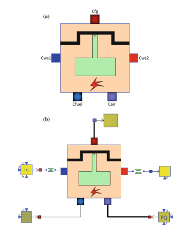
Internal Combustion Model in OpenModellica (ThermosysPro book Image):
a.) Icon of Internal Combustion Engine
b.) Model of Internal Combustion Engine
The diagram above shows the IC Engine modelled in OpenModellica which I will then further on try to accomplish, uses the following components:
• One InternalCombustionEngine component model;
• One SourcePQ component model (for the flue gases);
• One Sink component model (for the flue gases);
• One SourcePQ component model (for water/steam);
• One Sink component model (for water/steam);
• One FuelSourcePQ component model (for the fuel).
the InternalCombustionEngine component receives:
(1) the air pressure, mass flow rate, temperature, and composition at the inlet;
(2) the fuel pressure, mass flow rate, temperature, lower heat value, and composition at the inlet; and
(3) the water pressure, mass flow rate, and specific enthalpy at the inlet.
The component computes
(1) the flue gases temperature, pressure, and composition at the outlet;
(2) the water pressure and specific enthalpy at the outlet;and
(3) the mechanical and electrical power produced by the engine.
The following parameters for this test case, I will use the parameters on a modern IC Engine which is a Car Engine and then try my best to model a electric vehicle model in OpenModellica to compare that results and see which has better Mechanical Power and better Efficiency.
OpenModellica Modelling
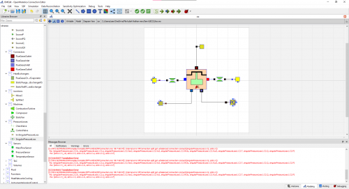
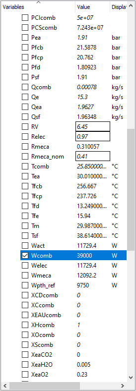
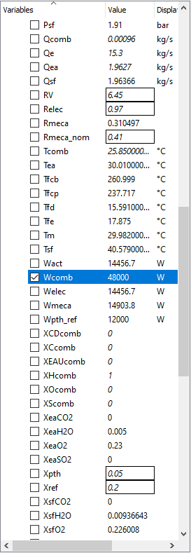
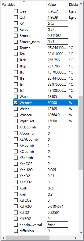
With my Modelling of an Internal Combustion Engine in Open modellica, I have not yet achieved the main purpose and that is to formalize the model and further applying the parameters due to the errors.
The test parameters below:
• Mechanical efficiency type = 2
• a (x2 coefficient of the linear mechanical efficiency) = − 5.4727 � 10−9
• b (x coefficient of the linear mechanical efficiency) = 4.9359 � 10−5
• c (constant coefficient of the linear mechanical efficiency) = 0.30814
• Engine electrical efficiency = 0.97 • Thermal loss fraction to the cooling water = 0.05
• Thermal loss fraction to the ambient = 0.2 • Gas average molar mass = 20 g/mol
• Water pressure loss as percent of the pressure at the inlet = 1%
• Pressure difference between the inlet and the outlet (air–flue gases) = 0
• Engine volume ratio = 6.45 • Compression polytropic coefficient = 1.28
• Expansion polytropic coefficient = 1.33 • Air temperature at the inlet = 303.16 K
• Air pressure at the inlet = 1.91 � 105 Pa
• Air mass flow rate at the inlet = 1.9627 kg/s
• CO2 mass fraction in the air at the inlet = 0
yields the results:
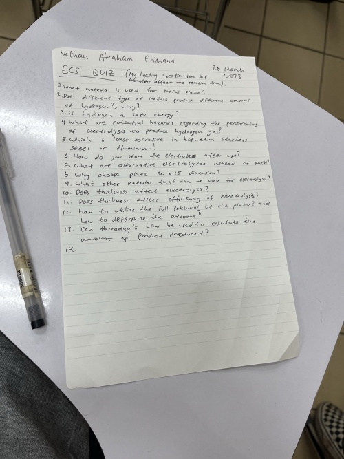
Quiz Energy Conversion System 2
PERSONAL PROJECT: Hydrolisis Experiment for IC Engine Experimenation in OpenModellica
Introduction
With this Personal Project, I intend to bring the effectiveness of promoters such as salts or aluminium oxide on the rate of the Hydrolysis Process and if it has an effect on the outcome.
The personal project is designed for students to learn on creativity and more towards hands on learning, with the personal projecy on hydorlisis, we are expected to learn about the effects of different plate dimensions of differnet materials on the outcome it has on a hydrolisis process taken place.
With the material that I chose to be Aluminium of type 1100;
Furthermore on my Personal Project will be updated here on this part of my Air account.
Methods and Procedure
With the plate that I am using which is an Aluminium 1100 type with dimensions of 15x10 cm and a thickness of 1 mm.
Materials needed are:
1. Aluminium Plate 15x10 cm thickness 3 mm
2. Handheld grinder with metal cutting disk
3. Ruler or measuring tool
Procedure (preperation):
1. Measure the Aluminium plate to the dimensions given.
2. Cut up the plates to the appopriate dimensions.
3. Repeat for 4 other plates, 5 in total.
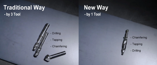
4. Drill Holes on all plates and taped to give threads as seen on illustration below.
5. align the threaded long rod into the threaded holes of the Aluminium 1100 plates.
Procedure (Experiment Hydrolysis):
Preperation:
1. Align the Holes to the Threaded rods and insert 2 threaded-nut-fastener in between each of the plates.
2. Repeat for all the plates, in total 5 plates.
Experimentation
1. Connect the anode to the Aluminium Plate configuration
2. Place the connector to the salt water
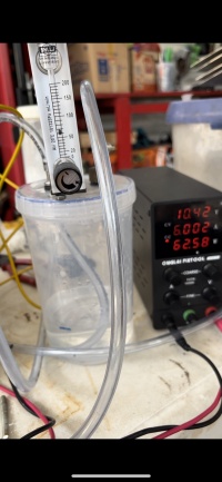
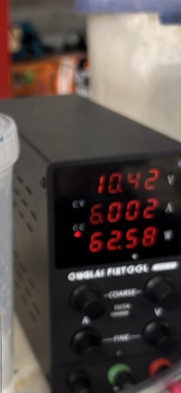
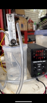
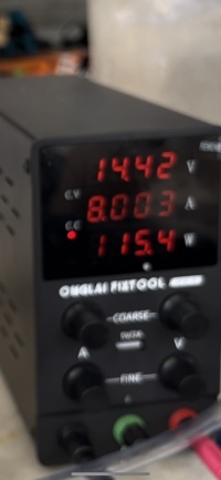
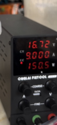
3. Turn on the amp meter and adjust for the Volt, Amp and Watt.
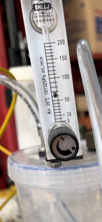
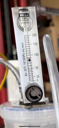
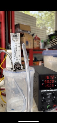
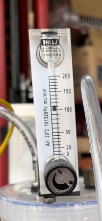
4. Analyze the hydrogen flow rates
5. Repeat for 3 different Ampers.
Results from Experiment
EXPERIMENT 1
Voltage: 10.42; Ampere: 6.002; Watt: 62.58
EXPERIMENT 2
Voltage: 14.42; Ampere: 8.003; Watt: 115.4
EXPERIMENT 3
Voltage: 16.72; Ampere: 9.000; Watt: 150.5
OpenModellica Experiment
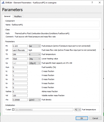
PARAMETER
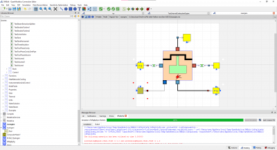
MODEL OPENMODELLICA
HYDROGEN MODELLING
MODEL OPENMODELLICA CODING
MODEL OPENMODELLICA RESULTS
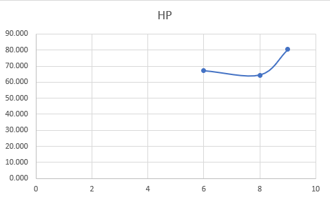
EXCEL DATA
EXCEL GRAPH
CONCLUSION
From this, I would suggest that the table and graphs are showing a sign of miss conduction due to minimal errors or slight errors due to calculation or even due to experiment and data taking errors.
PRESENTATION
https://docs.google.com/presentation/d/1IV--8hANAN66xJPEHv85DDvdmPEzSx5q_roctrnW-hM/edit?usp=sharing
FINAL PROJECT: Hydrolisis Experiment for torch and temperature rise
Final Paper:
https://docs.google.com/document/d/1xEDTU8vZxHoXlyroTdr1w3sr94sCvaRB50zOa9S5OxE/edit?usp=sharing
Slides:
https://docs.google.com/presentation/d/1IV--8hANAN66xJPEHv85DDvdmPEzSx5q_roctrnW-hM/edit?usp=sharing

