Difference between revisions of "Fourth Class Meeting - Timothy Felix Vickary"
(Created page with "== RESUME == <p align="justify">Coba pelajari software struktur itu seperti apa, karena di teknik mesin mencakup beban bangunan ada juga yang mengarah ke penentuan besar pipa,...") |
(→RESUME) |
||
| Line 1: | Line 1: | ||
== RESUME == | == RESUME == | ||
| − | <p align="justify"> | + | <p align="justify">Try to learn what structure software is, because in mechanical engineering it includes building loads that also lead to the determination of the size of the pipe, the cooling load and others. The theorem is generated from axioms and then becomes a proposition, this is already happening because we adhere to something exact mathematics, with mathematics can solve or prove a problem. The first approach used is a continuous concept, the object is considered to have a continuous nature. From there developed mathematical modeling. Up to the stokes navier equation, a mathematical equation for predicting fluid movements based on momentun and mass conservation laws. Just like software, if we say that objects have a rigid body that has particles interacting with each other continuously. We have to wonder about what software, what input and what output. We are not learning formulas, but how to use formulas. Economics is not used, because it uses minimum effort to get a big profit. |
| − | |||
| − | |||
| − | |||
</p> | </p> | ||
| + | |||
| + | ---- | ||
| + | |||
| + | ==ASSIGNMENT== | ||
| + | <div style="font-size:125%;">'''Introduction'''</div> | ||
| + | <p align="justify">SAP2000 software is a structural analysis program which is worldwide used. We can analyse the behaviour of particular object contain structure which material, loads, systemic structure can be assigned as we desired. SAP2000 helps us view mathematically the characteristic of object which has been imposed and the feasibility or might be the additional support to enhance and improve the safety of the structure. By using this software, we could learn how software help in saving significant amount of time from calculation in order to have a better reconstruction or redesign even new development on the model.</p> | ||
| + | |||
| + | <div style="font-size:125%;">'''Objective'''</div> | ||
| + | <p align="justify">Students have the ability to predict and measure the probable model of housing structure to be built.</p> | ||
| + | |||
| + | <div style="font-size:125%;">'''Method'''</div> | ||
| + | <p align="justify">First, we need to assign the grid lines. | ||
| + | |||
| + | [[File:4-1.png|center|thumb|upright=1.5|]] | ||
| + | |||
| + | Then we will have the object shown below. | ||
| + | |||
| + | [[File:4-2.png|center|thumb|upright=1.5|]] | ||
| + | |||
| + | Second, we need to establish our desired either length, wide, or height of the grid. | ||
| + | |||
| + | [[File:4-3.png|center|thumb|upright=1.5|]] | ||
| + | |||
| + | Shown below the result of modification of the grid lines. | ||
| + | |||
| + | [[File:4-4.png|center|thumb|upright=1.5|]] | ||
| + | |||
| + | Third we should assign the materials to be inserted later. | ||
| + | |||
| + | [[File:4-5.png|center|thumb|upright=1.5|]] | ||
| + | |||
| + | We set steel ASTM A500 just for instance | ||
| + | |||
| + | [[File:4-6.png|center|thumb|upright=1.5|]] | ||
| + | |||
| + | Below shown the property of material. Future assignment, we could assign the real material close to what Indonesian standard provides. | ||
| + | |||
| + | [[File:4-7.png|center|thumb|upright=1.5|]] | ||
| + | |||
| + | Fourth, we click the frame section submenu to have determine which shape of structure we are going to have. | ||
| + | |||
| + | [[File:4-8.png|center|thumb|upright=1.5|]] | ||
| + | |||
| + | [[File:4-9.png|center|thumb|upright=1.5|]] | ||
| + | |||
| + | [[File:4-10.png|center|thumb|upright=1.5|]] | ||
| + | |||
| + | [[File:4-11.png|center|thumb|upright=1.5|]] | ||
| + | |||
| + | [[File:4-12.png|center|thumb|upright=1.5|]] | ||
| + | |||
| + | [[File:4-13.png|center|thumb|upright=1.5|]] | ||
| + | |||
| + | [[File:4-14.png|center|thumb|upright=1.5|]] | ||
| + | |||
| + | Fifth, by doing some frame drawing we could get the actual column or structure of our model. | ||
| + | |||
| + | [[File:4-15.png|center|thumb|upright=1.5|]] | ||
| + | |||
| + | Sixth, we need to set the load imposed on the structure. | ||
| + | |||
| + | [[File:4-16.png|center|thumb|upright=1.5|]] | ||
| + | |||
| + | [[File:4-17.png|center|thumb|upright=1.5|]] | ||
| + | |||
| + | Various loads could be assigned, below shown live dead quake and wind. | ||
| + | |||
| + | [[File:4-18.png|center|thumb|upright=1.5|]] | ||
| + | |||
| + | [[File:4-19.png|center|thumb|upright=1.5|]] | ||
| + | |||
| + | Loads that we had already set, could also be combined | ||
| + | |||
| + | [[File:4-20.png|center|thumb|upright=1.5|]] | ||
| + | |||
| + | [[File:4-21.png|center|thumb|upright=1.5|]] | ||
| + | |||
| + | [[File:4-22.png|center|thumb|upright=1.5|]] | ||
| + | |||
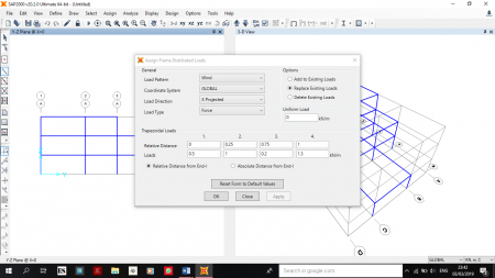
| + | Seventh, we set the loads we already mention to the structure as distributed loads. | ||
| + | |||
| + | [[File:4-23.png|center|thumb|upright=1.5|]] | ||
| + | |||
| + | [[File:4-24.png|center|thumb|upright=1.5|]] | ||
| + | |||
| + | [[File:4-25.png|center|thumb|upright=1.5|]] | ||
| + | |||
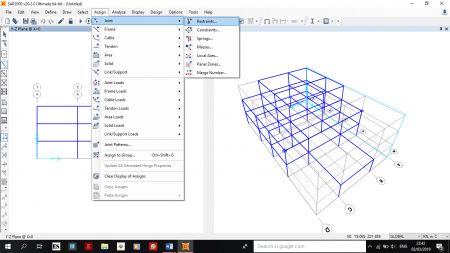
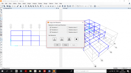
| + | As structure remain unwavering on the ground we set the restraint of its foundation. | ||
| + | |||
| + | [[File:4-26.png|center|thumb|upright=1.5|]] | ||
| + | |||
| + | [[File:4-27.png|center|thumb|upright=1.5|]] | ||
| + | |||
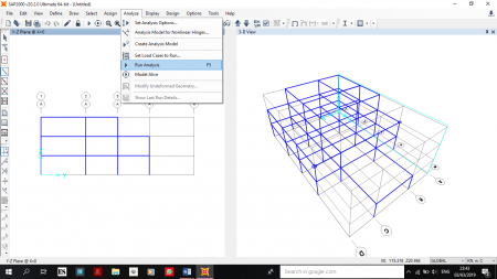
| + | Lastly, we could run the whole analysis of the load of the structure. | ||
| + | |||
| + | [[File:4-28.png|center|thumb|upright=1.5|]] | ||
| + | |||
| + | [[File:4-29.png|center|thumb|upright=1.5|]] | ||
| + | |||
| + | [[File:4-30.png|center|thumb|upright=1.5|]] | ||
| + | |||
| + | [[File:4-31.png|center|thumb|upright=1.5|]] | ||
| + | |||
| + | <div style="font-size:125%;">'''Result'''</div> | ||
| + | |||
| + | [[File:4-32.png|center|thumb|upright=1.5|]] | ||
| + | |||
| + | [[File:4-33.png|center|thumb|upright=1.5|]] | ||
| + | |||
| + | |||
| + | <div style="font-size:125%;">'''Conclusion'''</div> | ||
| + | <p align="justify">By having a trial on SAP2000 we have the rough idea how to utilize the advancement of a software to improve design and construction from engineer with ideal approach.</p> | ||
Revision as of 16:17, 23 March 2019
RESUME
Try to learn what structure software is, because in mechanical engineering it includes building loads that also lead to the determination of the size of the pipe, the cooling load and others. The theorem is generated from axioms and then becomes a proposition, this is already happening because we adhere to something exact mathematics, with mathematics can solve or prove a problem. The first approach used is a continuous concept, the object is considered to have a continuous nature. From there developed mathematical modeling. Up to the stokes navier equation, a mathematical equation for predicting fluid movements based on momentun and mass conservation laws. Just like software, if we say that objects have a rigid body that has particles interacting with each other continuously. We have to wonder about what software, what input and what output. We are not learning formulas, but how to use formulas. Economics is not used, because it uses minimum effort to get a big profit.
ASSIGNMENT
SAP2000 software is a structural analysis program which is worldwide used. We can analyse the behaviour of particular object contain structure which material, loads, systemic structure can be assigned as we desired. SAP2000 helps us view mathematically the characteristic of object which has been imposed and the feasibility or might be the additional support to enhance and improve the safety of the structure. By using this software, we could learn how software help in saving significant amount of time from calculation in order to have a better reconstruction or redesign even new development on the model.
Students have the ability to predict and measure the probable model of housing structure to be built.
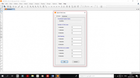
First, we need to assign the grid lines.
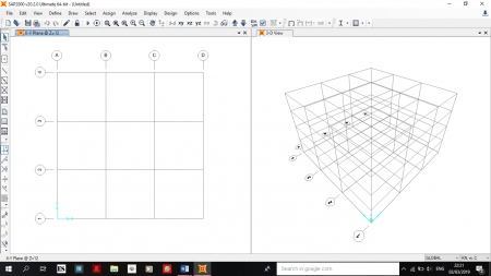
Then we will have the object shown below.
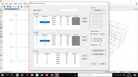
Second, we need to establish our desired either length, wide, or height of the grid.
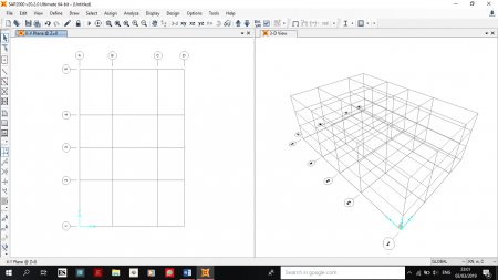
Shown below the result of modification of the grid lines.
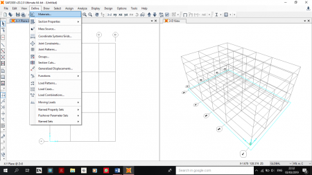
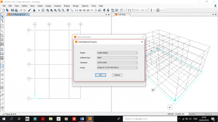
Third we should assign the materials to be inserted later.
We set steel ASTM A500 just for instance
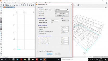
Below shown the property of material. Future assignment, we could assign the real material close to what Indonesian standard provides.
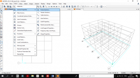
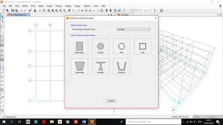
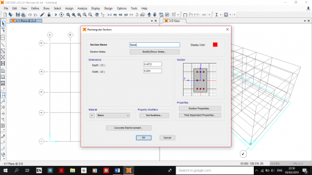
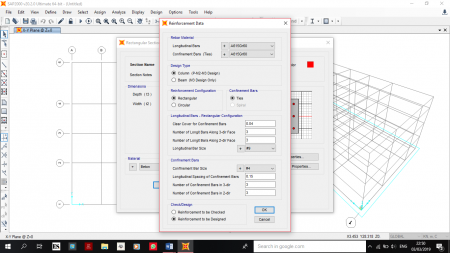
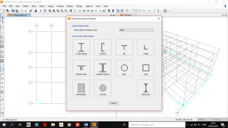
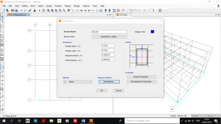
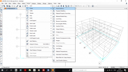
Fourth, we click the frame section submenu to have determine which shape of structure we are going to have.
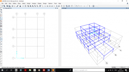
Fifth, by doing some frame drawing we could get the actual column or structure of our model.
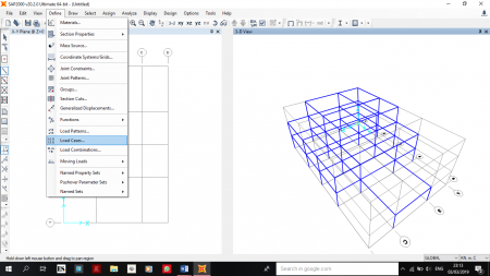
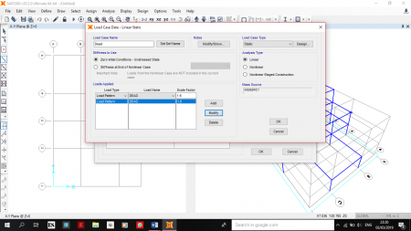
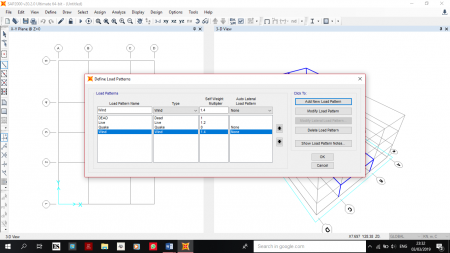
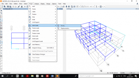
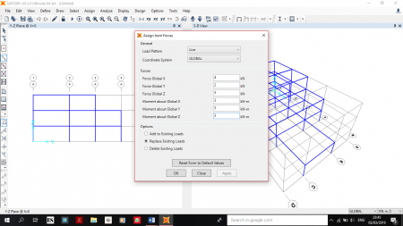
Sixth, we need to set the load imposed on the structure.
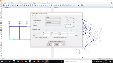
Various loads could be assigned, below shown live dead quake and wind.
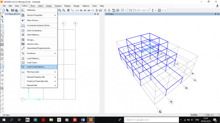
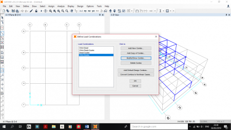
Loads that we had already set, could also be combined
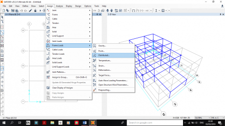
Seventh, we set the loads we already mention to the structure as distributed loads.
As structure remain unwavering on the ground we set the restraint of its foundation.
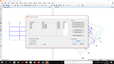
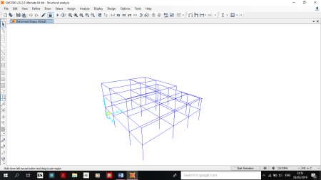
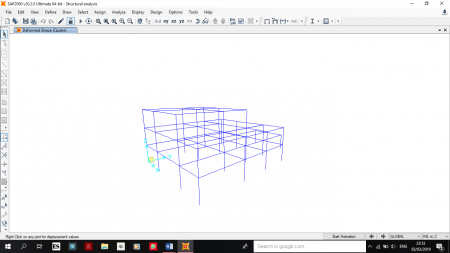
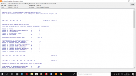
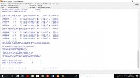
Lastly, we could run the whole analysis of the load of the structure.
