Fadhlan Dindra
Contents
- 1 Biodata
- 2 Numerical Method
- 3 Energy Conversion System 01
Biodata
PAGI TEKNIKK!! My name is Fadhlan Kiska Anargya Dindra and my friends casually call me Dindra. Currently studying Mechanical Engineering at the University of Indonesia. Fast learner, well-organized, and responsible person. Always look forward to doing something new. Have an interest in sports, arts, and automotive.
Name: Fadhlan Kiska Anargya Dindra
Date of Birth: September 7th, 2003
NPM: 2106658414
Major: Mechanical Engineering
E-mail: fadhlan.kiska@ui.ac.id
I made this blog for the purposes of Energy Conversion System 01 KKI that i took this semester. Special appreciation to Mr. DAI for creating this website to open new opportunities for us in learning through digital media. I will use this blog as my personal space to create my creativity in learning Numerical Method and Energy Conversion System 01 lectures.
Numerical Method
Session Review
23 May 2023 Class
As an introductory class, our lecturer Dr. Ahmad Indra Siswantara introduced himself and his focus of study on the concept of consciousness, and invites us to participate in the discussion on the importance of applying consciousness in our daily lives as well as the recurrence of difficult concepts in the problems that we face that remind us to practice consciousness about the limitations of human understanding. Outside class time, a follow-up discussion was conducted in the class group for practicing consciousness by inviting discussion on the most realistic solution of a typical limit problem. We were invited to explore the notion of infinity and the limitations of computing involving values that are typically referred to as 'undefined'. Lastly, our project for the remainder of the semester was introduced.
30 May 2023 Class
In todays class of Numerical Method, Pak DAI asked us to discuss the Hydrogen Tank Design and Optimization project within the class with every class member to gain better knowledge on developing our overall results. Throughout the class, the discussion was moderated by Patrick Samperuru as a replacement for the class coordinator, M. Jiddan Walta, who was at the time absent due to exchange matters. In this discussion, we started by making an outline on the project objective function which was to create a functional hydrogen tank design that is optimized following the constraint parameters of pressure at 8 bars, a capacity of 1 liter, and a maximum budget of 500,000 IDR. According to Benarido Amri, the ideal material for a high pressure cylinder has a very high tensile strength, a low density, and does not react with hydrogen or allow hydrogen to diffuse into it. Most pressure cylinders to date have used austenitic stainless steel. Patrick Samperuru then continued the discussion on the material by stating several potential materials that can be used based on the types of the hydrogen tanks, being type I of all metal, type II of metal with carbon fiber wrap, type III composite with metal lining, type IV composite with non-metal lining stating that type I and II is the most probable for the design. Next, M. Azkhariandra Aryaputra stated the importance of several design considerations such as storage tank design, safety measures, leakage mitigation, and material compatibility. Following the discussion of materials, Ariq Dhifan and Fadhlan Dindra added several materials that they want to use.
Next, we conversed the 3 main points needed in our optimization. This include the design variable, objective function, constraint which can be different for every class member. Patrick Samperuru started by explain that his objective function is to accommodate the use of hydrogen tanks in the field that is more complex and dynamic meaning it would need a constraint of a high strength and wear fatigue so that is can used for long term, which is achieved by choosing an all metal tank. For Vegantra Siaga, he wanted a pressure constraint because hydrogen storage systems often have pressure limits to ensure safe operation, where pressure constraints can be defined as upper and lower bounds on the hydrogen storage pressure that prevent the storage system from operating outside the desired pressure range. According to Faris Pasya, space and weight constraints can be used as well depending on the application, there may be limitations on the available space or weight of the pressurized hydrogen system. These constraints can influence the choice of tank size, material selection, and system layout. Next, M. Annawfal Rizky stated that he wants the constraint to be the compatibility with hydrogen, The tank material should be compatible with hydrogen gas to prevent any chemical reactions, embrittlement, or degradation that could affect the tank's performance or safety. Material selection is crucial to ensure compatibility and avoid hydrogen diffusion or leakage. For M. Ikhsan Rahadian, we chose safety due to the high pressure of hydrogen, and its highly flammable, the safety of the tank is very important. choosing the right material such as aluminum alloy 6061 can increase the strength and safety, and also choose the right design.
Pressurized Hydrogen Storage Case Study
Pressurized hydrogen storage is a method of storing hydrogen gas by compressing it to high pressures inside storage vessels or tanks. Pressurized hydrogen storage plays a vital role in enabling the utilization of hydrogen as a clean energy carrier. By effectively storing hydrogen gas at high pressures, it becomes more viable for various applications, contributing to the advancement of hydrogen-based technologies and the transition to a sustainable energy future. Our goals in this class are to finalized the design and optimization for Pressurized Hydrogen Storage but with the specification of gas being pressurized at 8 bars and volume is 1 liter.
A hydrogen tank, also known as a hydrogen storage tank, is a container designed to store hydrogen gas for various applications. Hydrogen tanks are an essential component of hydrogen fuel cell vehicles, industrial processes, and energy storage systems. They provide a means to store hydrogen safely and efficiently until it is needed for use.
Hydrogen tanks are designed with safety features such as pressure relief valves, burst discs, and leak detection systems to ensure safe operation and prevent overpressure or leaks. The tank design, material selection, and construction adhere to specific standards and regulations to ensure the integrity and safety of the hydrogen storage system.
It's important to note that the choice of hydrogen tank depends on various factors, including the specific application requirements, storage capacity, weight considerations, safety considerations, and system efficiency. Different technologies and tank designs offer trade-offs in terms of cost, storage capacity, weight, and safety, and the selection should be made based on the specific needs of the application.
Material Selection
To design a hydrogen tank with a gas pressure of 8 bars and a volume of 1 liter within a maximum cost of 500,000 IDR, several factors need to be considered, such as material selection, manufacturing process, and safety requirements.
4130 steel, also known as chromoly steel or alloy steel, is a low-alloy steel that contains chromium and molybdenum. It is commonly used in various applications, including aerospace, automotive, and structural components. For the material properties, 4130 steel offers a good balance of strength, toughness, and cost-effectiveness. It has a tensile strength of around 560-700 MPa (81,000-101,000 psi) and a yield strength of approximately 460-590 MPa (67,000-85,000 psi), depending on the heat treatment and condition. The addition of chromium and molybdenum improves the steel's hardenability, strength, and corrosion resistance compared to standard carbon steels.
4130 steel is generally compatible with hydrogen gas but may require appropriate surface treatment or coating to mitigate potential issues such as hydrogen embrittlement. Proper precautions should be taken during the manufacturing and handling processes to minimize hydrogen absorption and ensure long-term integrity. 4130 steel can be easily formed and welded, making it suitable for tank fabrication. Common manufacturing processes for 4130 steel tanks include seamless tube fabrication, welding (such as TIG or MIG welding), and heat treatment as needed.
Geometrical Constraint
In this case, i choose a Cylindrical Shape as the geometry of the tank because cylindrical tanks can maximize the use of available volume and allowing for efficient storage of hydrogen. Moreover, the cylindrical shape provides a larger internal volume compared to other shapes with the same external dimensions. For the structural, cylindrical tanks distribute stress uniformly along the walls, resulting in a structurally efficient design. The cylindrical shape inherently provides good resistance against internal pressure, making it suitable for high-pressure hydrogen storage.
Surface Area Optimization
By minimizing the surface area of the cylindrical geometry, we can optimized the budget-cost without compromising safety factors and reducing existing specifications. To know the minimum radius and minimum height, we can do some iteration in python (or another coding software). The iteration in the provided code is achieved using nested loops. The outer loop iterates over different radius values, while the inner loop iterates over different height values. This combination of nested loops allows for systematically considering various combinations of radius and height for the cylindrical structure.
The process of systematically exploring all possible combinations of values using nested loops is commonly referred to as "nested iteration" or "nested looping". In this specific case, it helps to iterate through all the possible radius and height values within the specified range to find the cylindrical structure with the minimum surface area that meets the minimum capacity requirement.
import math

def calculate_surface_area(radius, height):
    # Calculate the surface area of a cylinder
    base_area = math.pi * radius**2
    lateral_area = 2 * math.pi * radius * height
    total_area = 2 * base_area + lateral_area
    return total_area

def find_minimum_surface_area(min_capacity):
    min_surface_area = float('inf')
    best_radius = 0
    best_height = 0

    for radius in range(1, 101):  # Consider radii from 1 to 100
        for height in range(1, 101):  # Consider heights from 1 to 100
            volume = math.pi * radius**2 * height
            if volume >= min_capacity:
                surface_area = calculate_surface_area(radius, height)
                if surface_area < min_surface_area:
                    min_surface_area = surface_area
                    best_radius = radius
                    best_height = height

    return best_radius, best_height

# Specify the minimum capacity in liters
min_capacity_liters = 1

# Convert the minimum capacity to cubic centimeters (1 liter = 1000 cubic centimeters)
min_capacity = min_capacity_liters * 1000

# Find the cylindrical structure with the minimum surface area
radius, height = find_minimum_surface_area(min_capacity)

# Print the results
print("Minimum Surface Area Cylindrical Structure:")
print(f"Radius: {radius} cm")
print(f"Height: {height} cm")
print(f"Surface Area: {calculate_surface_area(radius, height)} cm^2")
print(f"Volume: {math.pi * radius**2 * height} cm^3")
After that, we can run the code and the result as follows:
Minimum Surface Area Cylindrical Structure:
Radius: 5 cm
Height: 13 cm
Surface Area: 565.4866776461628 cm^2
Volume: 1021.0176124166828 cm^3
Hoop stress, also known as circumferential stress or tangential stress, is a type of stress that occurs in a cylindrical or spherical object, such as a pipe or a pressure vessel. It is caused by the internal pressure acting on the walls of the object and tends to stretch or expand the object circumferentially. For knowing its hoop stress, we can calculate using iteration in python by input the 8 bars pressure to its iteration.
r = 5e-2 # The radius value
p = 800000 # Gas being pressurized at 8 bars
t = 2.5e-3 # minimum thickness

while t < 10e-3:
  hoop = (r * p)/(t)
  print('for thickness', t, 'hoop stress =', hoop, "Pa")
  t += 0.1e-3
  if hoop > 435e9: # Yield strength for AISI 4130
    break
Result:
for thickness 0.0025 hoop stress = 16000000.0 Pa
for thickness 0.0026 hoop stress = 15384615.384615386 Pa
for thickness 0.0026999999999999997 hoop stress = 14814814.814814817 Pa
for thickness 0.0027999999999999995 hoop stress = 14285714.285714287 Pa
for thickness 0.0028999999999999994 hoop stress = 13793103.448275866 Pa
for thickness 0.002999999999999999 hoop stress = 13333333.333333338 Pa
for thickness 0.003099999999999999 hoop stress = 12903225.806451617 Pa
for thickness 0.003199999999999999 hoop stress = 12500000.000000004 Pa
for thickness 0.0032999999999999987 hoop stress = 12121212.121212127 Pa
for thickness 0.0033999999999999985 hoop stress = 11764705.882352946 Pa
for thickness 0.0034999999999999983 hoop stress = 11428571.428571435 Pa
for thickness 0.003599999999999998 hoop stress = 11111111.111111118 Pa
for thickness 0.003699999999999998 hoop stress = 10810810.810810817 Pa
for thickness 0.003799999999999998 hoop stress = 10526315.78947369 Pa
for thickness 0.0038999999999999977 hoop stress = 10256410.256410263 Pa
for thickness 0.0039999999999999975 hoop stress = 10000000.000000006 Pa
for thickness 0.004099999999999998 hoop stress = 9756097.560975615 Pa
for thickness 0.004199999999999998 hoop stress = 9523809.523809528 Pa
for thickness 0.004299999999999998 hoop stress = 9302325.581395352 Pa
for thickness 0.0043999999999999985 hoop stress = 9090909.090909094 Pa
for thickness 0.004499999999999999 hoop stress = 8888888.888888892 Pa
for thickness 0.004599999999999999 hoop stress = 8695652.173913045 Pa
for thickness 0.004699999999999999 hoop stress = 8510638.297872342 Pa
for thickness 0.0048 hoop stress = 8333333.333333334 Pa
for thickness 0.0049 hoop stress = 8163265.306122449 Pa
for thickness 0.005 hoop stress = 8000000.0 Pa
for thickness 0.0051 hoop stress = 7843137.2549019605 Pa
for thickness 0.005200000000000001 hoop stress = 7692307.692307691 Pa
for thickness 0.005300000000000001 hoop stress = 7547169.811320754 Pa
for thickness 0.005400000000000001 hoop stress = 7407407.407407406 Pa
for thickness 0.005500000000000001 hoop stress = 7272727.272727271 Pa
for thickness 0.005600000000000002 hoop stress = 7142857.142857141 Pa
for thickness 0.005700000000000002 hoop stress = 7017543.859649121 Pa
for thickness 0.005800000000000002 hoop stress = 6896551.724137928 Pa
for thickness 0.0059000000000000025 hoop stress = 6779661.01694915 Pa
for thickness 0.006000000000000003 hoop stress = 6666666.666666663 Pa
for thickness 0.006100000000000003 hoop stress = 6557377.049180325 Pa
for thickness 0.006200000000000003 hoop stress = 6451612.903225803 Pa
for thickness 0.0063000000000000035 hoop stress = 6349206.349206346 Pa
for thickness 0.006400000000000004 hoop stress = 6249999.999999996 Pa
for thickness 0.006500000000000004 hoop stress = 6153846.15384615 Pa
for thickness 0.006600000000000004 hoop stress = 6060606.060606057 Pa
for thickness 0.0067000000000000046 hoop stress = 5970149.253731339 Pa
for thickness 0.006800000000000005 hoop stress = 5882352.941176467 Pa
for thickness 0.006900000000000005 hoop stress = 5797101.449275358 Pa
for thickness 0.007000000000000005 hoop stress = 5714285.71428571 Pa
for thickness 0.007100000000000006 hoop stress = 5633802.816901404 Pa
for thickness 0.007200000000000006 hoop stress = 5555555.555555551 Pa
for thickness 0.007300000000000006 hoop stress = 5479452.0547945155 Pa
for thickness 0.007400000000000006 hoop stress = 5405405.4054054 Pa
for thickness 0.007500000000000007 hoop stress = 5333333.333333328 Pa
for thickness 0.007600000000000007 hoop stress = 5263157.894736838 Pa
for thickness 0.007700000000000007 hoop stress = 5194805.19480519 Pa
for thickness 0.0078000000000000074 hoop stress = 5128205.128205123 Pa
for thickness 0.007900000000000008 hoop stress = 5063291.139240501 Pa
for thickness 0.008000000000000007 hoop stress = 4999999.999999995 Pa
for thickness 0.008100000000000007 hoop stress = 4938271.604938268 Pa
for thickness 0.008200000000000006 hoop stress = 4878048.780487801 Pa
for thickness 0.008300000000000005 hoop stress = 4819277.108433732 Pa
for thickness 0.008400000000000005 hoop stress = 4761904.761904759 Pa
for thickness 0.008500000000000004 hoop stress = 4705882.352941174 Pa
for thickness 0.008600000000000003 hoop stress = 4651162.790697672 Pa
for thickness 0.008700000000000003 hoop stress = 4597701.149425286 Pa
for thickness 0.008800000000000002 hoop stress = 4545454.545454544 Pa
for thickness 0.008900000000000002 hoop stress = 4494382.022471909 Pa
for thickness 0.009000000000000001 hoop stress = 4444444.444444444 Pa
for thickness 0.0091 hoop stress = 4395604.395604395 Pa
for thickness 0.0092 hoop stress = 4347826.0869565215 Pa
for thickness 0.0093 hoop stress = 4301075.268817205 Pa
for thickness 0.009399999999999999 hoop stress = 4255319.148936171 Pa
for thickness 0.009499999999999998 hoop stress = 4210526.315789474 Pa
for thickness 0.009599999999999997 hoop stress = 4166666.666666668 Pa
for thickness 0.009699999999999997 hoop stress = 4123711.3402061868 Pa
for thickness 0.009799999999999996 hoop stress = 4081632.653061226 Pa
for thickness 0.009899999999999996 hoop stress = 4040404.040404042 Pa
for thickness 0.009999999999999995 hoop stress = 4000000.000000002 Pa
From the result of the thickness above, we can take the mean from 2 mm to 9.9 mm which is around 6 mm of the thickness. Therefore, we already got the suitable specifications for the tank.
Radius: 5 cm
Height: 13 cm
Thickness: 6 mm
Cost Budgeting
To calculate the price of a cylindrical tank, we need to consider the cost of the material and the manufacturing process.
Specification:
Radius (R) = 5 cm
Height (H) = 13 cm
Surface Area (A) = 565.4866776461628 cm^2
Volume (V) = 1021.0176124166828 cm^3
Thickness (T) = 6 mm = 0.6 cm
Material: 4130 steel
The material cost is typically based on the weight of the material required. Since we have the surface area and thickness, we can calculate the weight of the material using the formula:
Weight = Surface Area * Thickness * Density
The density of 4130 steel is approximately 7.85 g/cm^3.
Weight = 565.4866776461628 cm^2 * 0.6 cm * 7.85 g/cm^3 Weight = 2649.097 g = 2.649097 kg (approx.)
The cost of the material can vary, but for estimation purposes, let's assume a cost of 29.668 IDR per kg of 4130 steel (This price is the rough approximation based on the internet).
Material Cost = Weight * Cost per kg Material Cost = 2.649097 kg * 29.668 IDR Material Cost = 78.590 IDR (approx.)
Then, we can approximate the manufacturing process cost is around 50.000 IDR
Total Cost = Material Cost + Manufacturing Cost Total Cost = 78.590 IDR + 50.000 IDR Total Cost = 128.590 IDR (approx.)
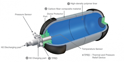
Therefore, the estimated price of the cylindrical tank with the given specifications (Radius: 5 cm, Height: 13 cm, Surface Area: 565.4866776461628 cm^2, Volume: 1021.0176124166828 cm^3, Thickness: 6 mm, Material: 4130 steel) would be approximately 128.590 IDR. But please note that the price of the tank may vary due to the price difference or the certain specification of the steel. Also, there are some tools that are not included in the calculation like the port, pressure sensor, dome protector, polymer linen with high-density specification, and so on. But overall, this design has not passed even far from the specified budget limit.
Conclusion
The cylindrical shape is the most suitable geometry for hydrogen tank since cylindrical shape can efficiently utilized volume, uniform stress distribution, ease of fabrication, and integration flexibility. Tank has a volume of 1021.02 cm³, which exceeds the minimum required capacity of 1 liter (1000 cm³). Therefore, it meets the minimum capacity requirement.
For the material, 4130 steel is a commonly used material in pressure vessel applications due to its high strength, good weldability, and resistance to deformation under pressure. It is a suitable material choice for the hydrogen tank. In conclusion, based on data and calculation above, the hydrogen storage tank with a radius of 5 cm, height of 13 cm, and made of 4130 steel appears to be suitable. The tank meets the minimum capacity requirement of 1 liter, and the choice of a cylindrical shape, along with the selected material, is appropriate for the pressurized hydrogen storage application.
My Conscious Efforts in Numerical Method Learning and its Application in Hydrogen Storage Design Optimization
My presentation video can be accessed on: https://www.youtube.com/watch?v=tuaOrQ4YyXo
I am My Consciousness is a very good phrase to implement in everyday life. After waking up in the morning, we consciously rushed to campus to learn something. While on campus, we must consciously pay attention to the lecturer. When doing assignments, quizzes, or homework, we also have to be conscious and serious when doing it. Without realizing it, we actually always implement I am My Consciousness on our daily basis.
In terms of Numerical Method lectures, we can correlate them with the consciousness theory. For example, We consciously recognize that the expression (X^2 - 1) /(X-1) becomes undefined when X is equal to 1. But, when we're conscious enough to solve it, there will be an exact result by canceling the number first before directly calculating it. Therefore, consciousness is relevant in understanding the significance of division by zero and recognizing the undefined result in this particular case.
Nothing is achieved without obstacles and struggles. Our knowledge limitation and the time bound must be the one. However, when we are conscious and widely open our eyes, nowadays, access to academic journals or other sources is very easy to obtain. We can put much effort on reading journals and learning new things outside the class to gaining out knowledge. When we start struggling, just remember and conscious that there is The Creator who will always make things easier for us.
MESIN!!! BERSYUKUR BERSYUKUR BERSYUKUR!!!
Energy Conversion System 01
Session Review
30 October 2023 Class
ِبِسْمِ اللَّهِ الرَّحْمَنِ الرَّحِيْم
In our first class session, Pak DAI asked about how we were feeling and our academics. Most of us said that we were okay and ready to continue the Energy Conversion System 1 lecture.
What Einstein said about education:
- Everybody is genius.
- Education is what remains after one has forgotten what one has learned in school.
Understanding things can be divided into three levels: the first level is knowing "what" something is, the second level is knowing "how" it works, and the third level is understanding "why" it matters.
If we use these three levels to think about energy, we can start with the "what" by looking at the equation: dE/dt = W+Q. This equation helps us describe energy.
A basic idea about energy is that it can't be made or destroyed; it just changes from one form to another. In real-life examples like pumps and turbines, we see this change happening. To make this change as effective as possible, we need to grasp the concept of efficiency. Efficiency in pumps is all about comparing the energy you put in to the energy you get out.
If you want to understand things better, you can think of it as digging into the ground. The more you dig, the deeper your understanding goes.
1 November 2023 Class
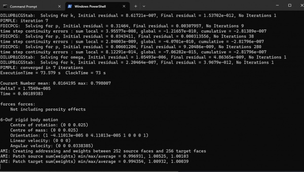
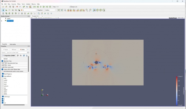
In our second class with Mr. DAI, we were going to CFD Lab in DTM Building level 3. As soon as we started a class, Bang Edo taught us how to make simulation of the VAWT or Vertical-Axis Wind Turbine using CFDSOF and Paraview Application.
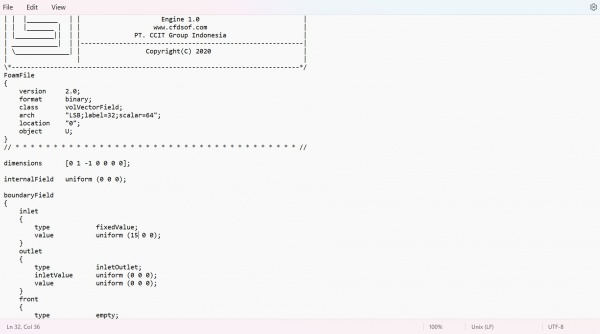
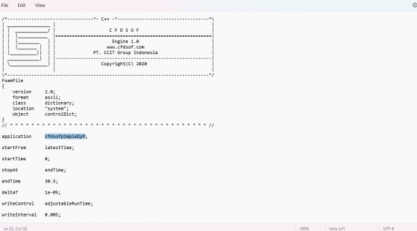
Before we open the Paraview, we were asked to download CFDSOF Application and then try to download the given VAWT (Vertical axis Wind Turbine) file on the WhatsApp Group. After the VAWT file downloaded, we need to run the CFDSOF Application from command prompt and write some specific script that given in the VAWT file.
The result is set by velocity 15 m/s (Bang Edo used 8 m/s for the simulation). After doing a computation and iteration for a moment in the command prompt, we get about 0.02 s for the time of simulation.
8 November 2023 Class
In delving into the intricacies of simulation, a pedagogical approach is adopted, employing a streamlined rendition of a turbine characterized by the presence of a mere two blades. This deliberate simplification serves as a strategic entry point for grasping the fundamental nuances embedded within the Computational Fluid Dynamics (CFD) simulation software.
By paring down the turbine to its essential components, namely the twin blades, the learning process is optimized, providing a structured environment for comprehending the underlying principles of CFDSOF software. This deliberate reduction in complexity facilitates a stepwise exploration of the software's functionalities, enabling individuals to navigate its features and intricacies with greater ease.
Through this simplified turbine model, the focus shifts towards unraveling the core elements governing energy conversion. A foundational comprehension is sought, wherein the conversion of energy becomes an enlightening exercise grounded in the principles of kinetic energy, potential energy, pressure, and velocity.
The two-blade turbine serves as a canvas upon which the intricate dance of energy unfolds. As the simulation unfolds, learners are guided through the dynamic interplay of kinetic and potential energy, the nuanced role of pressure in the system, and the ever-changing velocity profiles that dictate the turbine's performance.
This deliberate reduction in complexity not only facilitates a more digestible learning curve but also empowers individuals to gain a profound understanding of the basic formulae underpinning energy conversion within the context of fluid dynamics. Through this hands-on exploration, learners are equipped with a solid foundation, laying the groundwork for a more sophisticated comprehension of turbine dynamics and, by extension, broader applications of the CFDSOF software in complex engineering scenarios.
Static 2-Dimensional Simulation of a Single Blade
Parameters
- Box geometry properties: 1 m X 3 m X 1 m
- Base mesh: 10 m X 10 m X 0.1 m
- Velocity reference value: 0.01 m/s
- Simulation mode: Steady-state, laminar, and incompressible
- Initial condition = Fixed value velocity with 0 m/s speed
Pressure Results
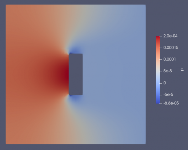
In the graphic provided, there is a noticeable area of increased pressure located on the front side of the blade. This heightened pressure is a potential factor contributing to the turbine's rotation around its axis. In theory, a greater surface area on the blade would result in more pressure generated at the front. Nevertheless, it's important to note that a larger surface area requires more material, consequently adding weight to the structure.
Velocity Results
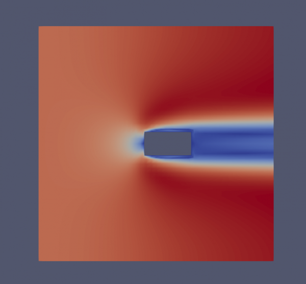
The figure above reveals several noteworthy observations:
- The left input side displays a relatively consistent pattern.
- A small region directly in front of the blade exhibits a velocity of 0.
- The segment covered by the blade demonstrates comparatively lower velocity.
- Conversely, the regions above and below the blade showcase the highest velocity among all the areas.
The heightened velocity in area 4 can be easily understood as a mechanism employed by the fluids to uphold a consistent flow rate within the control volume. This is encapsulated in the equation Q1 = Q2 or V1 * A1 = V2 * A2. Due to the obstruction introduced by the blade, the control volume's area decreases. Consequently, to maintain the same output flow rate, the velocity of the air must increase. This phenomenon gives rise to the distinct shape and pattern observed in the figure above.
Centrifugal Compressor Force Comparison
السلام عليكم ورحمة الله وبركاته
Hello everyone!!! So in this opportunity I would like to share my understanding about Centrifugal Compressor on the link video below.
Here is my video presentation link: https://www.youtube.com/watch?v=iyVU8Uuj15k
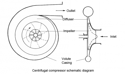
A centrifugal compressor uses a spinning blade to suck in air, pushing it toward the center, creating pressure and energy. Before the air goes to the middle of the spinning part, its energy changes to pressure through a diffuser and volute. The compressor has stages that each handle part of the overall pressure increase.
This type of compressor is dynamic and radial, unlike ones that keep a steady flow. It works at a constant pressure, affected by things like changes in temperature.
Air gets pulled into the middle of a spinning part with blades and is pushed toward the center by a spinning force. This movement makes the air pressure go up, creating energy.
Before the air goes into the center, its energy becomes pressure by going through a diffuser and volute. In modern versions, really fast electric motors power the spinning part, making a small compressor without a gearbox and oil system. This makes it oil-free and good for things that need completely oil-free air.
Advantages of Centrifugal Compressors:
- High Flow Rates: Centrifugal compressors are well-suited for applications requiring high flow rates of compressed air or gas.
- Compact Design: They typically have a more compact design compared to other compressor types, making them suitable for installations with space constraints.
- Low Maintenance: Centrifugal compressors often have fewer wearing parts than other compressor types, resulting in lower maintenance requirements and longer service intervals.
- High Efficiency: They can achieve high compression ratios with good efficiency, making them energy-efficient in certain operating conditions.
- Wide Range of Applications: Centrifugal compressors find applications in various industries, including petrochemical, power generation, and refrigeration.
Disadvantages of Centrifugal Compressors:
- Limited Pressure Ratios: Centrifugal compressors may have limitations in achieving very high pressure ratios compared to other compressor types like reciprocating compressors.
- Less Effective at Low Flows: They may be less effective at low flow rates, and their efficiency can be compromised in turndown conditions.
- Sensitive to Changes in Inlet Conditions: Performance can be affected by changes in inlet conditions such as fluctuations in temperature and pressure.
- Higher Initial Cost: The initial capital cost of centrifugal compressors can be higher than some other compressor types.
Usage in Real Life:
- Air Conditioning and Refrigeration: Centrifugal compressors are commonly used in large-scale air conditioning and refrigeration systems due to their efficiency and ability to handle high capacity requirements.
- Natural Gas Processing: They are employed in the oil and gas industry for natural gas processing, providing compression for gas transportation and processing.
- Power Generation: Centrifugal compressors are used in power plants for applications such as gas turbine air compression and the handling of process gases.
- Chemical and Petrochemical Industries: These compressors play a crucial role in chemical and petrochemical processes, where large volumes of gases need to be compressed.
- Aerospace Industry: Centrifugal compressors are utilized in aircraft engines for their compact design and ability to handle high flow rates.
Assumptions for Force Calculation
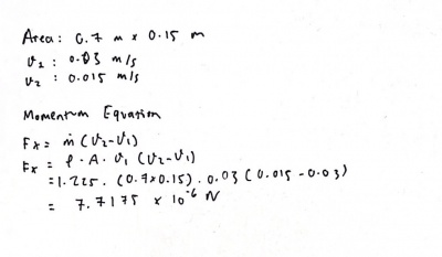
- Steady-state, laminar, incompressible
- Area = 0.7 m x 0.15 m
- Air density = 1.225 kg/m^3
- v1 = 0.03 m/s
- v2 = 0.015 m/s
Simulation
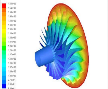
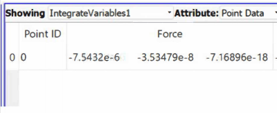
From the simulation, the result of the force on a single blade is -7.5432 x 10^-6 N in the x-axis.
Manual Calculation
From the procedural formula outlined in the manual, we can leverage the alteration in momentum, as illustrated in the accompanying figure. This approach involves making certain assumptions, specifically setting the velocity 2 at 0.015 m/s and the velocity 1 at 0.03 m/s. Additionally, we consider the flow rate velocity, which is determined by the utilization of velocity 1 in the calculation.
The manual calculation yielded a result force of 7.7175 x 10^-6 N.
Analysis
- Fx(Simulation) = -7.5432 x 10^-6 N
- Fx(Calculation) = 7.7175 x 10^-6 N
Both doing the math by hand and using a computer simulation gave us pretty similar answers. But there's a key difference: when we did the math by hand, we got a positive result, meaning there's a force going in one direction. In the simulation, though, the result was negative, suggesting a force in the opposite direction. This difference might be because we made different assumptions when figuring out the force. In the manual calculation, we focused on the force from the wind hitting the blade. In the simulation, it was the other way around, looking at the force the blade puts on the wind.
Hydraulic and Pneumatic
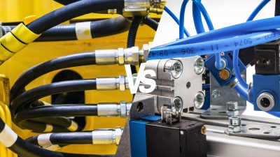
Hydraulic and pneumatic systems are both types of fluid power systems that use liquids or gases, respectively, to transmit power. These systems are widely used in various industries for tasks such as lifting, moving, pressing, and controlling machinery.
Hydraulic Systems:
1. Working Fluid: Hydraulic systems use incompressible fluids, typically hydraulic oil, as the working fluid. The fluid is pumped through a system of pipes, hoses, and cylinders to transmit force.
2. Components: The main components of a hydraulic system include a hydraulic pump, hydraulic fluid, hydraulic cylinders or motors, control valves, and hydraulic pipes or hoses.
3. Power Transmission: Hydraulic systems are known for their ability to transmit high forces and handle heavy loads. They are commonly used in applications where precise and powerful force control is required.
4. Advantages:
- High force transmission.
- Precise control of force and speed.
- Suitable for heavy-duty applications.
5. Disadvantages:
- Hydraulic oil can leak.
- Components can be heavy and bulky.
- Maintenance and repair can be more complex.
Commonly used in heavy machinery, construction equipment, automotive brake systems, and other applications requiring high force and precision.
Pneumatic Systems:
1. Working Fluid: Pneumatic systems use compressible gases, usually air, as the working fluid. Air is compressed and then released to perform mechanical work.
2. Components: The main components of a pneumatic system include a compressor, pneumatic cylinders, control valves, and pneumatic pipes or hoses.
3. Power Transmission: Pneumatic systems are suitable for applications where moderate force and speed are required. They are commonly used in tasks such as lifting, gripping, and moving lightweight objects.
4. Advantages:
- Lightweight components.
- Quick response times.
- Relatively simple maintenance.
5. Disadvantages:
- Lower force transmission compared to hydraulic systems.
- Compressed air can be less efficient than hydraulic fluid.
- Limited in applications involving heavy loads.
Widely used in manufacturing, assembly lines, robotics, and various industrial applications where lighter loads and faster response times are acceptable.
Steam Turbine Report
Introduction and Conscious Thinking
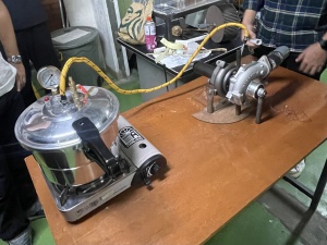
When we want to solve some solution, the first thing to do is establish our intention consciously. In this case, we need to keep in mind that we intend to learn about how the steam turbine works. Special appreciation to our friend, Amato, who willingly made the steam turbine from the turbo that Mr. DAI him. After our intention is established, we need to think about its initial problem, in example; how to make the steam turbine from the turbo, what cycle that used in the system, etc. After that, we can develop its model and design to solve all of the problems.
A turbocharger for a steam turbine isn't exactly a common concept, as steam turbines themselves operate on a fundamentally different principle compared to internal combustion engines where turbochargers are typically used.
Traditionally, steam turbines utilize high-pressure steam to directly drive the turbine blades, which then rotate a shaft connected to a generator or other machinery. The pressure of the steam gradually decreases as it expands through the turbine stages, ultimately exiting at a much lower pressure.
In contrast, a turbocharger in an internal combustion engine extracts energy from the exhaust gases to drive a compressor, which then forces more air into the combustion chamber, leading to a power boost. Steam turbines, on the other hand, don't have exhaust gases in the traditional sense, as the steam condenses after exiting the turbine.
Rankine Cycle
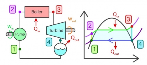
The representation of a steam turbine system often involves utilizing the conceptual framework of an ideal Rankine cycle, which comprises four integral components: the pump, boiler, turbine, and condenser.
- Isentropic Compression (Process 1-2): The water undergoes isentropic compression in the pump, increasing its pressure from a saturated liquid state.
- Isobaric Heat Addition (Process 2-3): The high-pressure liquid is heated at constant pressure in the boiler, transforming it into a saturated or superheated vapor.
- Isentropic Expansion (Process 3-4): The high-pressure, high-temperature vapor expands through the turbine, converting thermal energy to mechanical work.
- Isobaric Heat Rejection (Process 4-1): The low-pressure vapor is condensed back into a liquid in the condenser by rejecting heat to a cooling medium.
The Rankine cycle finds widespread application in steam power plants due to its effectiveness and efficiency in transforming thermal energy into mechanical work. It can be adapted for various purposes, including combined heat and power (CHP) systems or geothermal power plants, through the adjustment of parameters like pressures, temperatures, and fluid properties.
Calculation
To obtain the data and calculation, each student must have one full experiment and the volume should be different to get different data. In this trial, my volume was 500 ml and then we can calculate the time to reach the pressure that we want.
- Volume: 0.5 l
- Time: 10.83 s
When energy is added to the system, the related value will be positive. Conversely, if the energy exits the system, the corresponding value will also be positive.
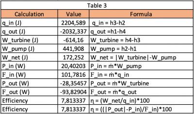
To streamline the calculation of the system's efficiency, a spreadsheet is created. Usually, this spreadsheet includes three main tables, arranged based on the significance of the variables and parameters at hand.
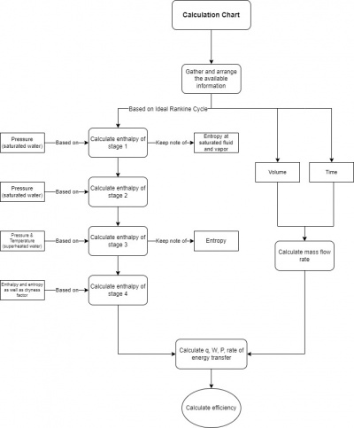
The flowchart below are the steps for determining the steam turbine system efficiency.
- Table 1 contains the value of enthalpy and entropy.
- Table 2 contains the value of mass flow rate, volume, and pressure.
When energy is supplied to the system, the associated value will be positive. Likewise, if the energy departs from the system, the corresponding value will also be positive.
- Table 3 contains the value of work, heat, power, energy, and efficiency.
Assumptions:
Generalize the machine to align with the conventional Rankine cycle. Calculate the enthalpy value of stage 2 using the pressure from the property table. Temperature is determined solely through estimation. Assume P1 equals P4 and P2 equals P3.
Result
From the calculation we get the Power which are:
- Pin = 20.351 W
- Pout = 28.28 W
And also we can get the efficiency of the system :
- Efficiency = 7.81%
Conclusion and Conscious Effort
The efficiency of this system is low which about 7.81%, but this number is not bad because we use using very simple and minimal tools. After we got the efficiency, we can conclude that our conscious thinking helps us to do this experiment. From we got our intension to calculate the efficiency. This experiment makes me more conscious and inspires me to carry out daily activities with conscious thinking.

