Draft1
abstract
Computational fluid dynamics (CFD) is robust in predicting and analyzing complex multiphase flow hydrodynamics, especially on fluid catalytic cracking (FCC) phenomena in fluid-solid reaction. This study presented the replacement valve as a regulator of the catalyst's distribution from the Regenerator to the Riser in a pilot-scale fluid catalytic cracking (FCC). On a large scale, FCC applies Slide valves/plug valves as a regulator of the catalyst rate from the Regenerator to the Riser also stops nitrogen flow Riser. However, Slide valves are carefully designed with abrasion-resistant protection for improving the reliability of the valve. Internal insulation allows to use of carbon steel for the body of the valves. It is impossible on a pilot plant scale because the dimeter pipe is small, making the catalyst often stuck in the valve and nitrogen escapes to the Riser. The solution is chiffon or layered U pipe by flowing the air below to regulate the catalyst and solve the Riser's nitrogen leakage. This study uses the CFD approach, specifically the MMPIC and DEM models, including the preliminary validation with catalyst dimension based on the Geldart group A and A ' Miyauchi.
Introduction
Indonesia sepanjang 2019 mencapai 51,8 juta ton CPO, dari sumber tersebut dapat di olah menjadi green fuel, sebelum menjadi Green Fuel, CPO di olah dahulu menjadi Bleached and Deodorized Palm Oil (RBDPO) 100% kemudian di proses dengan metode Fluid Catalytic Cracking (FCC). The process of the FCC unit consists of the feed injection system, riser, riser outlet separator system, disengager/stripper, regenerator, catalyst cooler (optional), catalyst withdrawal well, catalyst transfer lines, and control systems. Product pengolahan RBDPO dengan menggunakkan FCC yang utama adalah Gasoline, LCO (light cycle oil) dan LPG.
Proses FCC adalah reaksi hydrocarbon antara crude oil (RBDPO) dengan catalyst, berdasarkan The Geldart Classification of Particles katalist pada FCC di golongkan pada group A dan Region A', Miyauchi menggolongkan katalis berdasarkan group A’ dengan properties diameter 50-70 Micron. The proper selection of catalyst is very important to successful residue cracking operations. The importance of magnifies as the percentage of residual oil increases in the feedstock. Several properties of the catalyst should be examined for a particular feed. The properties are, Zeolite content, Micro-activity, Rare earths content, Unit cell size, Coke selectivity, Particle size distribution, Bulk density, Thermal stability, Surface area, Pore volume and pore distribution (strippability), Attrition resistance, Metals resistance, Gasoline octane properties. Regenerator dan riser adalah peralatan yang menentukan hasil product dari FCC sehingga pada paper ini menjelaskan transport katalis dari regenerator ke riser.
Untuk mempelajari fenomena katalis pada FCC menggunakan hydrodynamics melalui pendekatan Computational Fluid Dynamics (CFD), pada pendekatan simulasi gas dan particle terdapat beberapa jenis metode yaitu, Eulerian, MPPIC, DEM. Setiap jenis metode memiliki karakteristik masing pada penyelesain masalah gas-particle, pada MPPIC adalah pendekatan dengan parcel in cell di mana solids model tracks the position and trajectory of computational parcels, statistical groups of particles that share the same physical characteristics (e.g. diameter and density). In the present formulation, different diameter particles of the same material must be defined as separate solid phases, each with its own statistical classification, pada paper ini mengnakan CFDSOFT sebagai device untuk menghitung fenomena katalist pada FCC.
The multiphase particle-in-cell (MP-PIC) numerical method for predicting dense gas-solids flow. The MP-PIC method is a hybrid method such as IBM method, where the gas-phase is treated as a continuum in the Eulerian reference frame and the solids are modeled in the Lagrangian reference frame by tracking computational particles. The MPPIC is a derivative of the Particle-in-Cell (PIC) method for multiphase flows and the method employs a fixed Eulerian grid and Lagrangian parcels are used to transport mass, momentum, and energy through this grid in a way that preserves the identities of the different materials associated with the particles. The main distinction with traditional Eulerian-Lagrangian methods is that the interactions between the particles are calculated on the Eulerian grid. The Eulerian-Lagrangian method and the multiphase particle in cell (MPPIC) method have been used in this study. The model of the MPPIC is a Model Collision in CFDSOF, first of all, PIC models are derived from a Liouville equation describing the time evolution of a particle distribution function.
where X is particle position, ܷUm is particle velocity, p m is particle density, ܸ Vm is particle volume, and t is time. The subscript ݉m is indicative of nodding to solids phase ݉, which in this case would indicate a unique solids class of particles.
Here ∇ um is the divergence operator with respect to the velocity, ܷUm and A m is the discrete particle-phase acceleration. The particle distribution function integrated over velocity and mass will yield the likely number of particles per unit volume at the position, X, at time t, for small intervals of (Vm + dVm, pm + dpm, Um + dUm). The solids volume fraction, Es, can then by represented through the distribution function using a volume integral.
The solids phase is coupled to the Eulerian governing equations through the interphase momentum transfer term. Allowing Igm to be the contribution due to interphase momentum transfer between the gas and the m th solid phase, Where Dm is drag coefficient and ∇ p is pressure gradient.
1.1 Mathematical model MPPIC
The word particle, a single piece of material, spherical in nature, having physical characteristics that can be uniquely defined (like density, chemical composition, etc.); the word parcel indicates a statistical collection of particles of similar physical characteristics.
Conservation of Mass
The conservation of mass (or continuity equation) for the p th MPPIC parcel is given by managing the particle’s statistical weight, Wp, and considering its mass change, dm/dt, under the effects of a chemical reaction.
where R pn is the rate of production/consumption of the n th chemical species, and Np is the number of chemical species. This is not unlike the conservation of mass equation defined in Musser and Carney (2020). Specifically, the right-hand side of (eq above) accounts for interphase mass transfer because of heterogeneous chemical reactions or physical processes, like evaporation. In non-chemically reactive simulations (or those without phase change), the right side of Equation (eq above) equals zero.
Conservation of Species Mass
The n th species mass conservation equation for the MMPIC parcel is given by:
Where X pn is the n th chemical species mass fraction, and R pn is the rate of formation of species mass attributed to chemical reactions or physical processes. In non-chemically reactive simulations (or those without phase change), the right side of Equation (above) equals zero.
Conservation of Translational Momentum
The general conservation of translation momentum for the p th MMPIC parcel in the i th coordinate direction is given by:
where ܷU i is the parcel velocity, and ݃g i is the gravity body force. The first term on the right-hand side is the gravitational body force. The second term is a PIC-specific term derived from interparticle stress, described in detail in the section Interparticle Stress below.
As expected, the position of a parcel is related to its velocity through:
where Xi is the parcel position in the ݅i th coordinate direction.
Interparticle Stress
The interparticle stress variable follows the form suggested by Snider (2001). Specifically,
where E cp indicates a pre-determined, problem-specific, close-pack volume fraction for the solids phase. P s is an empirical pressure constant relatable to the scale and unit of the problem under evaluation, and B is an empirical unitless exponent, usually between 2 and 5. alpha is a tiny constant (e.g. 1e-7) to assure a non-zero denominator in calculations.
Conservation of Internal Energy
The general conservation of internal energy for the p th MMPIC parcel follows the same theoretical underpinnings as DEM. The internal energy is presented in terms of temperature. For an isothermal parcel (a PIC assumption),
where C p and ܶT are parcel specific heat and temperature (same as particle values). The first term on the right-hand side represents changes in internal energy accompanying species formation or destruction from a chemical reaction and/or phase change (h pn is the n the species-specific enthalpy) The last term, S p is a general source term. Note that S p might represent particle-particle heat transfer (currently 0 in PIC; there is no conduction model), fluid-particle heat transfer (convection), or radiative heat transfer (currently 0 in PIC; radiation model is pending).
Pada studi ini juga melalakukan pemodelan dengan menggunkan metode DEM, Pemodelan dengan Computational Fluid Dynamics (CFD) coupling dengan DEM (Discrete element method), In such an approach, the trajectories of and the forces acting on individual particles are tracked directly. It offers a sound theoretical base to generally model the interactions between particles as well as with the surrounding fluid and screen wall. This cannot be achieved by widely used continuum methods such as two-fluid models, which have not, to date, been applied to simulate particle screen. In recent years, the CFD-DEM approach has been widely accepted as an effective tool to study various particle-fluid systems, as reviewed by different investigators. Despite the broad applications, only a few efforts have been reported to use the CFD-DEM method to study particle retention. Recently, Shaffee et al. used a CFD-DEM model to study the effect of adhesion on particle filtration by a screen and demonstrated that an increase in particle adhesion reduces the porosity and pressure drop across the sand pack covering the screen. These CFD-DEM studies have demonstrated the feasibility of this method in modeling sand screen, to some degree. However, to date, CFD-DEM studies on the influences of slot width-particle size ratios and wetting fluids on screen retention performance have not been reported in the literature. Besides, none of the previous CFD-DEM studies have attempted to analyze particle-fluid flow characteristics and force structures to understand the screen retention performance and identify the underlying mechanisms.
1.2 Mathematical model CFD-DEM
The current CFD-DEM model is based on the model used to simulate hydraulic conveying. For brevity, only the key features of the model are outlined below. However, detailed modeling and numerical treatments can be found elsewhere.
Particle motion
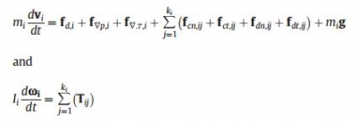
In the DEM model, the translational and rotational motion of a particle is governed by Newton's second law of motion, formulated as follows:
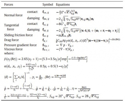
where mi is the particle mass, Ii is the moment of inertia, vi is the particle translational velocity, ωi is the particle angular velocity, and ki is the number of particle/wall in contact with particle i. The translational motion of a particle is caused by the particle-fluid interaction forces including the drag force, fd, i. The pressure gradient force, f∇p, i and the viscous force, f∇. τ, i, the gravitational force, mig and the inter-particle contact forces such as the elastic force, fc, ij and the viscous damping force, fd, ij. The rotational motion is caused by the inter-particle contact forces due to particle/wall j which generate torques, Tij causing particle I to rotate. The particle motions are calculated based on a soft-sphere contact model proposed originally by Cundall and Strack, and the inter-particle contact forces are calculated according to the Hertzian contact theory. The equations used to calculate the interparticle contact forces and particle-fluid interaction forces involved in Eq. 1 are listed in Table 1.
Fluid flow
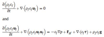
In the CFD model, the fluid flow is modeled in a similar way as those in the two-fluid model in the form of model A, in which the pressure is shared by both the liquid and solid phases [29,36]. The governing equations include the continuity equation and the Navier-Stokes equations:
where ρf is the fluid density, uf is the fluid velocity and p is the pressure, τ is the divergence of stress tensor that includes viscous and Reynolds
Table 1 The contact forces and particle-fluid interaction forces considered in the current model.
Dengan menggunakan pendekatan MMPIC dan DEM mampu menjelaskan hydrodynamic pada FCC. Pada skala besar FCC proses transfer katalis dari regenerator ke riser di atur oleh sliding valve atau dengan pluge valve. Akan tetapi pada skala pilot plant dengan diameter pipa transfer adalah 2 inch tidak di munggkinkan dengan menggunakan sliding valve karena sering terjadi stuck pada saat proses buka dan tutup untuk mengatur volume katalis menuju riser. Untuk itu dalam studi ini menjelaskan aplikasi seal loop untuk mengatur katalis pada FCC skala pilot plant.


