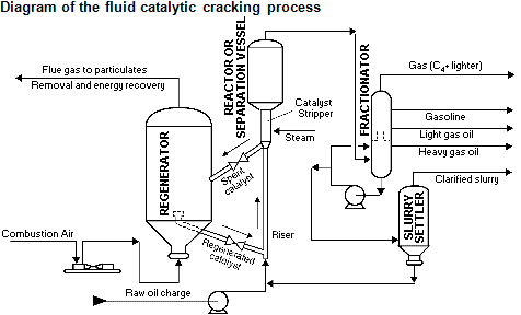
Fluid catalytic cracking Plant
Background
The process of the FCC unit consists of the feed injection system, riser, riser outlet separator system, disengager/stripper, regenerator, catalyst cooler (optional), catalyst withdrawal well, catalyst transfer lines, and control systems.
The feed mixture is pumped to the base of the riser and divided into equal flows, to each of the feed nozzles. The feed, which has been preheated, is finely atomized and mixed with dispersion steam in the feed nozzles and injected into the riser. The small droplets of feed contact hot regenerated catalyst in a counter-current way and vaporize immediately. The vaporized oil intimately mixes with the catalyst particles and cracks into lighter, more valuable products along with slurry oil, coke, and gas. The product vapors travel up the riser while carrying the catalyst. Residence time in the riser is approximately 2 seconds at design conditions. The specially designed feed injection system ensures the reaction is carried out efficiently to minimize the production of coke, gas, and slurry oil.
Feed injection zone
Oil feed to the riser is preheated before entering the reaction system. Preheat temperature along with regenerated catalyst temperature is controlled to result in an optimum catalyst to oil ratio. Passivator injection into the fresh feed just ahead of the feed nozzles acts to inhibit the undesirable effects
Dispersion steam is supplied to each of the feed nozzles to promote atomization and vaporization of the feed. The flow to each of the feed nozzles is adjusted by flow controllers.
Upstream the feed injection, stabilization steam is injected in the riser, through the stabilization steam injectors, in order to promote a smooth and homogeneous catalyst flow at the feed injection point. The flow to each of the injectors is adjusted by flow controllers
Riser/Reactor
The sensible heat, heat of vaporization, and heat of reaction required by the feed is supplied by the hot regenerated catalyst. The riser outlet temperature is controlled by the amount of regenerated catalyst admitted to the riser through the regenerated catalyst slide valve. In the wye section at the base of the riser, steam is injected via a steam ring to keep the regenerated catalyst in a fluid state at all times.
The cracking reactions take place during the two-second residence time in the riser as the reaction mixture accelerates toward the Riser Outlet Separator System (ROSS).
The catalyst is quickly separated from the hydrocarbon/steam vapors in the ROSS separator located at the end of the riser. This separation is necessary to discourage the undesirable continuation of reactions that produce gas at the expense of gasoline.
This system drastically reduces the post riser catalyst/vapors contact time. After exiting the ROSS separator, the vapors pass through high efficiency single stage cyclones to complete the separation of catalyst from vapors, thus minimizing the amount of catalyst lost into the product.
The reactor pressure "floats on" the main fractionator pressure and as such is not directly controlled at the converter section. The ROSS separator and disengager cyclones separate the product vapors from the spent catalyst and return the catalyst to the stripper bed. The cyclone diplegs are equipped with trickle-valves to prevent reverse flow of gas up the diplegs. Also, the ROSS separator is equipped with diplegs fitted on its pre-stripping chambers. These diplegs are sealed into the stripper catalyst bed in order to avoid any possibility of vapors back mixing.
