Difference between revisions of "Muhammad Alif Luthfi"
(→Simulation of Internal Combustion Engine using OpenModelica) |
|||
| Line 30: | Line 30: | ||
; 2. fuelSourcePQ | ; 2. fuelSourcePQ | ||
''ThermoSysPro.Combustion.BoundaryConditions.FuelSourcePQ'' | ''ThermoSysPro.Combustion.BoundaryConditions.FuelSourcePQ'' | ||
| − | This is the fuel source of the engine, parameters such as the fuel composition and flow rate can be changed. | + | : This is the fuel source of the engine, parameters such as the fuel composition and flow rate can be changed. |
| − | |||
; 3. sourceAir | ; 3. sourceAir | ||
''ThermoSysPro.FlueGases.BoundaryConditions.SourcePQ'' | ''ThermoSysPro.FlueGases.BoundaryConditions.SourcePQ'' | ||
| − | This is the air source of the engine, parameters such as the air pressure and flow rate can be changed. | + | : This is the air source of the engine, parameters such as the air pressure and flow rate can be changed. |
| − | |||
; 4. sink | ; 4. sink | ||
''ThermoSysPro.FlueGases.BoundaryConditions.Sink'' | ''ThermoSysPro.FlueGases.BoundaryConditions.Sink'' | ||
| − | This is the exhaust of the engine (sink). | + | : This is the exhaust of the engine (sink). |
| − | |||
; 5. SourcePQ_Water | ; 5. SourcePQ_Water | ||
''ThermoSysPro.WaterSteam.BoundaryConditions.SourcePQ'' | ''ThermoSysPro.WaterSteam.BoundaryConditions.SourcePQ'' | ||
| − | This is the water cooling system inlet of the engine, the enthalpy and flow rate of the coolant can be changed. | + | : This is the water cooling system inlet of the engine, the enthalpy and flow rate of the coolant can be changed. |
| − | |||
; 6. Sink_Water | ; 6. Sink_Water | ||
''ThermoSysPro.WaterSteam.BoundaryConditions.Sink'' | ''ThermoSysPro.WaterSteam.BoundaryConditions.Sink'' | ||
| − | This is the water cooling system outlet of the engine. | + | : This is the water cooling system outlet of the engine. |
| − | |||
; 7. singularPressureLoss | ; 7. singularPressureLoss | ||
''ThermoSysPro.WaterSteam.PressureLosses.SingularPressureLoss'' | ''ThermoSysPro.WaterSteam.PressureLosses.SingularPressureLoss'' | ||
| − | This component simulates the pressure loss within the cooling system. | + | : This component simulates the pressure loss within the cooling system. |
Revision as of 22:32, 27 February 2023
Hello everyone, this page will be the wiki for my Energy Conversion System 2 Class.
The connection between the sugar cane industry, battery industry, and oil and gas industry.
Me: Are there any connection between the sugar cane industry, battery industry, and oil and gas industry
ChatGPT: Yes, there are connections between the sugar cane industry, battery industry, and oil and gas industry.
One connection between the sugar cane industry and the battery industry is through the production of biofuels. Sugar cane can be used to produce ethanol, which is a biofuel that can be blended with gasoline to reduce greenhouse gas emissions. Ethanol can also be used as a fuel for fuel cells, which are used to power electric vehicles. Additionally, some types of batteries, such as flow batteries, can use sugars as an electrolyte.
Another connection between the sugar cane industry and the oil and gas industry is through the production of bioplastics. Bioplastics can be made from sugar cane or other plant-based materials, which can reduce the dependence on fossil fuels for plastic production. However, some bioplastics still require oil and gas derivatives in their manufacturing process.
The connection between the battery industry and the oil and gas industry is through the production of lithium-ion batteries, which are commonly used in electric vehicles and other electronic devices. Lithium is a rare metal that is typically mined from the earth, and some of the largest lithium deposits are found in areas that also produce oil and gas, such as the lithium triangle in South America. Additionally, the production and disposal of batteries can have environmental impacts, which are often linked to the production and consumption of fossil fuels.
Overall, while there are connections between these industries, efforts are being made to reduce the dependence on fossil fuels and minimize the environmental impacts of their operations.
Internal Combustion Engine Personal Project
Title: Ammonia as an alternative fuel for Internal Combustion Engine (ICE)
Ammonia (NH3) is a lesser-known alternative fuel for ICEs. It is very similar to Hydrogen, in that they do not produce greenhouse gas when burned. It also brings additional benefits in the form of ease of storage. However, in terms of performance, how does it fare against conventional gasoline and hydrogen fuels? Also, What drawbacks does it bring?. In this project, I will try to answer these questions.
Simulation of Internal Combustion Engine using OpenModelica
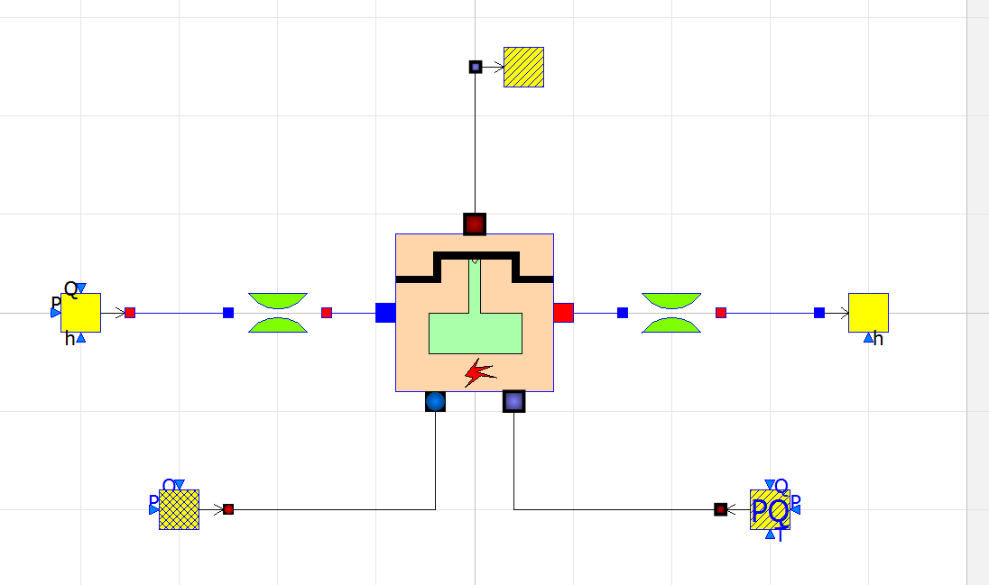
There are 7 components that governs the simulation of an Internal Combustion Engine in OpenModelica
- 1. alternatingEngine
ThermoSysPro.MultiFluids.Machines.AlternatingEngine This is the main component in the model, this component solves the equations for Internal Combustion Engine to obtain the power output of the engine.
- 2. fuelSourcePQ
ThermoSysPro.Combustion.BoundaryConditions.FuelSourcePQ
- This is the fuel source of the engine, parameters such as the fuel composition and flow rate can be changed.
- 3. sourceAir
ThermoSysPro.FlueGases.BoundaryConditions.SourcePQ
- This is the air source of the engine, parameters such as the air pressure and flow rate can be changed.
- 4. sink
ThermoSysPro.FlueGases.BoundaryConditions.Sink
- This is the exhaust of the engine (sink).
- 5. SourcePQ_Water
ThermoSysPro.WaterSteam.BoundaryConditions.SourcePQ
- This is the water cooling system inlet of the engine, the enthalpy and flow rate of the coolant can be changed.
- 6. Sink_Water
ThermoSysPro.WaterSteam.BoundaryConditions.Sink
- This is the water cooling system outlet of the engine.
- 7. singularPressureLoss
ThermoSysPro.WaterSteam.PressureLosses.SingularPressureLoss
- This component simulates the pressure loss within the cooling system.
