Difference between revisions of "Ariq Dhifan"
Ariq Dhifan (talk | contribs) (→Conclusion) |
Ariq Dhifan (talk | contribs) (→Conclusion) |
||
| (One intermediate revision by the same user not shown) | |||
| Line 275: | Line 275: | ||
And the efficiency of this experiment both calculation of insulting power and heat is: | And the efficiency of this experiment both calculation of insulting power and heat is: | ||
* 7,81337 % | * 7,81337 % | ||
| − | This system is noteworthy enough while converting turbocharger to steam turbine generator. | + | This system is noteworthy enough while converting turbocharger to steam turbine generator. with conscious thinking we realized that we can evaluate what is the shortcoming of this experiment and we are desire to reevaluate to have a better output of this experiment of steam turbine generator. |
'''For furthermore explanation, you can check my youtube video about my report :''' | '''For furthermore explanation, you can check my youtube video about my report :''' | ||
| − | + | https://www.youtube.com/watch?v=67FYKoOPZ1Y | |
===Conscious Effort=== | ===Conscious Effort=== | ||
Latest revision as of 08:55, 29 December 2023
Contents
- 1 Introduction
- 2 Case Study of Pressurized Hydrogen Storage
- 3 Substance That Contained
- 4 Pressure Tank Material
- 5 Coding
- 6 Cost Constraints
- 7 Design and Conclusions
- 8 Energy Conversion System 1 Class
- 8.1 1st Class Summary
- 8.2 CFD Simulation using CFDSOF
- 8.3 CFDSOF Torque calculation
- 8.4 Single Blade CFDSOF Simulation
- 8.5 Simple Blade Simulation
- 8.6 Centrifugal Fan and Compressor Overview
- 8.7 Force Result Difference Between Simulation and Manual Calculation
- 8.8 My Conscious Effort
- 8.9 Hydraulics and Pneumatics
- 9 STEAM TURBINE
- 10 Semester Final Reflection
Introduction
Name: Ariq Dhifan
NPM: 2106657323
Major: Mechanical Engineering KKI
DoB: 22 June 2003
E-mail: ariqdhifan7@gmail.com
Assalamualaikum Hello Everyone! My name is Ariq Dhifan, an undergradute student majoring in Mechanical Engineering at Universitas Indonesia. Currently I am taking Numerical Method class with Pak DAI as my lecturer.
Case Study of Pressurized Hydrogen Storage
The effectiveness, security, and utility of the storage system are all improved as part of the process of optimizing pressurized hydrogen storage. Here are several essential factors for pressurized hydrogen storage optimization:
Tank Design and Materials: The storage tanks' design and materials are crucial to optimization. The tanks may be made out of strong, lightweight materials like high-strength metals or innovative composites while yet preserving structural integrity. Tank shapes that have been optimized can increase storage capacity while still fitting into the available area.
Safety precautions: When dealing with compressed hydrogen, safety is of the highest importance. Leaks may be avoided and the integrity of the storage tanks can be guaranteed by putting strong safety measures into place, such as strict manufacturing standards, quality control processes, and routine inspections. Effective pressure release and venting
Storage Pressure: The energy density and usability of the storage system are influenced by the pressure level at which hydrogen is kept in storage. A greater storage pressure makes it possible to store more hydrogen in a given container, but it also creates issues with tank weight, cost, and safety. Finding the ideal balance between storage pressure, energy density, and pragmatic concerns for the particular application is the goal of optimization.
Systems for Filling and Dispensing: Systems for filling and dispensing are essential for pressurized hydrogen storage. Systems that are optimized should reduce fill time, guarantee precise pressure control during filling, and enable safe and regulated hydrogen dispensing.
Thermal management: Controlling the storage tanks' temperature is crucial for achieving peak performance. Thermal insulation can minimize energy losses and keep the pressure within the appropriate range by reducing heat transfer to the hydrogen that has been stored. As needed, active cooling or heating systems can be used to control the temperature.
System Integration: When optimizing pressurized hydrogen storage, the transportation and end-use systems as well as the storage tanks must all be taken into account. To guarantee effective and flawless operation, integration with fuel cell systems or other hydrogen consumption technologies may be enhanced.
Cost Factors: When doing optimization, it is important to take into account all associated costs, such as those related to materials, production methods, and infrastructure needs. Pressurized hydrogen storage must be widely used, and this depends on finding affordable options that nevertheless retain performance and safety.
Substance That Contained
Hydrogen is a colorless, odorless gas. It is easily ignited. Once ignited it burns with a pale blue, almost invisible flame. The vapors are lighter than air. It is flammable over a wide range of vapor/air concentrations. Hydrogen is not toxic but is a simple asphyxiate by the displacement of oxygen in the air. Under prolonged exposure to fire or intense heat the containers may rupture violently and rocket. Hydrogen is used to make other chemicals and in oxyhydrogen welding and cutting.
Compressed hydrogen (CGH2, CH2 or CGH2) is hydrogen at its gaseous state but kept under pressure, typically at 350 bar (5,000 psi) and 700 bar (10,000 psi). This substance thus simplifies the issue of storing hydrogen, as this element in its gaseous state presents an excessively low density, which meant tank sizes needed to be enormous posing not only logistical but also safety issues. On the other hand, cryo compressed hydrogen is kept at cryogenic (-150º) temperatures, and presents a higher hydrogen density, thus pushing the storage possibilities further. While storing hydrogen has always represented a challenge, the discovery of efficient methods for it is boosting the so-called “hydrogen economy”. In fact, a number of options are being investigated today in search for the right one. At this point, the physical storage of compressed hydrogen in tanks stands out as the technology facilitating onboard automotive storage. Pressure values here remain between 350 and 700 bar (5,000 and 10,000 psi). The main difference would be developing a storage solution that is able not only to generate cryogenic temperatures, but also can be pressurized at nominal pressure levels of between 250-350 atm.
Pressure Tank Material
The density of 304 steel is around 8 g/cm3, or 0.289 lb/in3. Type 304 steel also comes into three main varieties: 304, 304L, and 304H alloys, which chemically differ based on carbon content. 304L has the lowest carbon percentage (0.03%), 304H has the highest (0.04-0.1%), and balanced 304 splits the difference (0.08%). In general, 304L is reserved for large welding components that do not require post-welding annealing, as the low carbon percentages increase ductility. Conversely, 304H is most used in elevated temperatures where the increased carbon content helps preserve its strength while hot.
Type 304 steel is austenitic, which is simply a type of molecular structure made from the iron-chromium-nickel alloy blend. It makes 304 steel essentially non-magnetic, and gives it a lower weakness to corrosion between grains thanks to austenitic steels being generally low carbon. 304 steel welds well using most welding methods, both with and without fillers, and it easily draws, forms, and spins into shape. AISI 304 will be my choice for the tank material due to its cost that relatively cheap and it is also a high-strength material. AISI 304 satisfy our variables in cost realm.
Coding
Initializing Surface Area for hydrogen tank
import numpy as np
from scipy.optimize import minimize
def objective(x):
# x[0] represents radius, x[1] represents height
radius = x[0]
height = x[1]
# Calculate the surface area of thte cylinder
surface_area = 2 * np.pi * radius * (radius + height)
return surface_area
def constraint(x):
# x[0] represents radius, x[1] represents height
radius = x[0]
height = x[1]
# Calculate the internal volume of the cylinder
volume = np.pi * radius**2 * height
# Difference between the volume and the desired value
return volume - 1000
# Initial value of radius and height
x0 = [5.0, 10.0]
# Variable constraints (radius and height)
bounds = [(0, None), (0, None)]
constraint_dict = {'type': 'eq', 'fun': constraint}
result = minimize(objective, x0, method='SLSQP', bounds=bounds, constraints=constraint_dict)
# Optimization results
print("Optimization results:")
print("Radius: {:.2f} cm".format(result.x[0]))
print("Height: {:.2f} cm".format(result.x[1]))
print("Surface Area: {:.2f} cm^2".format(result.fun))OUTPUT
Optimization results:
Radius: 5.52 cm
Height: 10.43 cm
Surface Area: 553.79 cm^2
Finding The Thickness of The Pressure Tank (8 bar)
r = 5.52e-2 # Tank Radius
p = 800000 # 8 Bar Pressure
t = 2.7e-3 # Minimum Thickness

while t < 11.05e-3:
  hoop = (p * r) / t
  print('Thickness', t, 'hoop stress =', hoop, "Pa")
  t += 1e-3
if hoop > 215e9: #Yield Strength of AISI 304
  break
OUTPUT
Thickness 0.0027 hoop stress = 16355555.555555554 Pa
Thickness 0.0037 hoop stress = 11935135.135135135 Pa
Thickness 0.0047 hoop stress = 9395744.680851063 Pa
Thickness 0.0057 hoop stress = 7747368.421052631 Pa
Thickness 0.0067 hoop stress = 6591044.776119403 Pa
Thickness 0.0077 hoop stress = 5735064.935064935 Pa
Thickness 0.0087 hoop stress = 5075862.068965518 Pa
Thickness 0.0097 hoop stress = 4552577.319587628 Pa
Thickness 0.010700000000000001 hoop stress = 4127102.8037383175 Pa
Cost Constraints
Due to our objective variable that limit our budget at Rp.500.000, We have done research on some distributor website that sell 2-10 mm thick Stainless steel 304 plates. With the thickness 5 mm thick, the material cost at Rp.133.000 with total dimension 5 mm x 20 cm x 20 cm. So, looking from this reference for 553,79 cm^2 surface area it costs around Rp.184.135 for 1 unit. The rest of cost we use to pay welding and labour fee. Overall, it satisfy our variable.
Design and Conclusions
From this design that we make using the good material option, analysis said that might be a little bit error of design when we give the tank design pressure at 8 bar there is some area that still red that cause crack or any other risks. Due to its durability, availability, and affordability, using AISI 304 stainless steel as a compressed hydrogen tank material is an excellent choice. However, during tank design and operation, elements like hydrogen embrittlement, a decreased strength-to-weight ratio, and a constrained operational temperature range should be carefully taken into this project.
Energy Conversion System 1 Class
1st Class Summary
Pak DAI told us about one of Einstein’s quotes that everyone is a genius.But it works when we also try hard and always believe in ourself that we can finish all of our task with a perfect finish. In my opinion about energy in the previous lecture, energy is a source potential that can't be produced or destroyed that helps us in our daily life with various forms. We can change or transform this energy to another form such as electricity to kinetic energy. Energy conversion, also termed as energy transformation, is the process of changing one form of energy into another. Energy conversion occurs everywhere and every minute of the day. There are numerous forms of energy like thermal energy, electrical energy, nuclear energy, electromagnetic energy, mechanical energy, chemical energy, sound energy, etc. On the other hand, the term Energy Transformation is used when energy changes forms from one form to another. Whether the energy is transferred or transformed, the total amount of energy doesn’t change, and this is known as the law of conservation of Energy.
CFD Simulation using CFDSOF
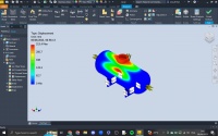
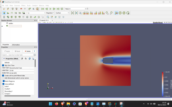
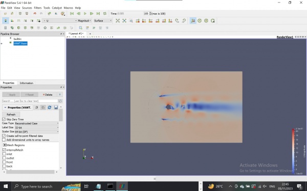
In this simulation, initial time = 0 s end time = 0.505 s inlet velocity of (11 0 0)
As the result, we can visualize it using Paraview
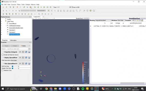
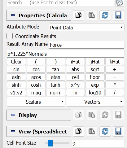
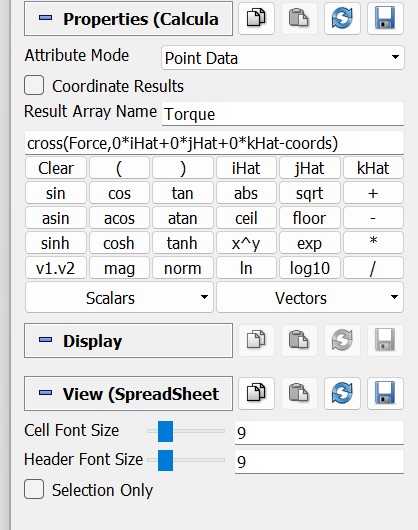
CFDSOF Torque calculation
Single Blade CFDSOF Simulation
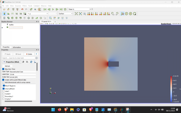
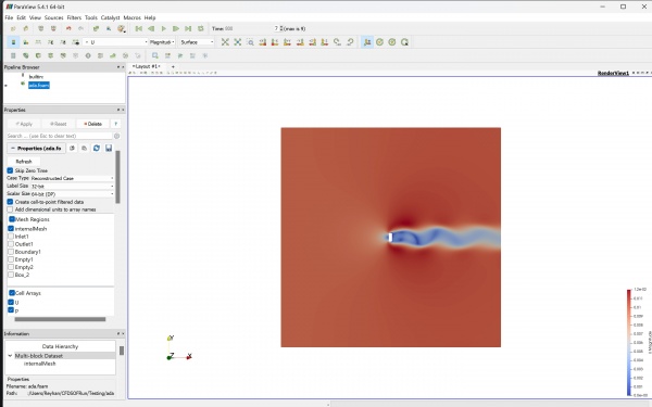
In this simulation we insert some paramaters value such as: Box geometry properties: 1 m X 3 m X 1 m Base mesh: 10 m X 10 m X 0.1 m Velocity reference value: 0.01 m/s Simulation mode (Steady-state, incompressible, laminar) Initial condition = 0 m/s
Simple Blade Simulation
In this simulation we insert some paramaters value such as: Box geometry properties: 1 m X 3 m X 1 m Base mesh: 10 m X 10 m X 0.1 m Velocity reference value: 0.01 m/s Simulation mode (Steady-state, incompressible, laminar) Initial condition = 0 m/s
Centrifugal Fan and Compressor Overview
A centrifugal fan is a mechanical device for moving air or other gases in a direction at an angle to the incoming fluid. Centrifugal fans often contain a ducted housing to direct outgoing air in a specific direction or across a heat sink; such a fan is also called a blower, blower fan, or squirrel-cage fan (because it looks like a hamster wheel). Tiny ones used in computers are sometimes called biscuit blowers. These fans move air from the rotating inlet of the fan to an outlet. They are typically used in ducted applications to either draw air through ductwork/heat exchanger, or push air through similar impellers. Compared to standard axial fans, they can provide similar air movement from a smaller fan package, and overcome higher resistance in air streams.
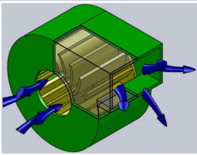
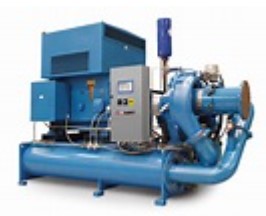
A centrifugal compressor is a mechanical device that compresses a fluid with the help of the impeller’s radial acceleration, which is surrounded by the compressor housing. In a centrifugal compressor, the air or gas enters axially in the impeller and discharges radially. Therefore, it is also called a radial compressor. In the centrifugal compressor, the impeller increases the speed of the working fluid (gas or air) by converting the kinetic energy of the air/gas into speed. But the diffuser further converts the speed of the air or gas into pressure energy.
Force Result Difference Between Simulation and Manual Calculation
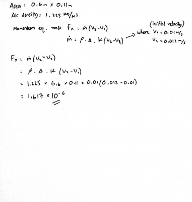
ASSUMPTION
- Area = (0.6 x 0.11) m
- Air Density = 1,225 kg/m3
- Steady State, Laminar, Incompressible
ANALYSIS From 2 different calculation, we got a value of -1.9327e-6 (Software Simulation) and 1,617e-6 (Manual Calculation). The results obtained from both the manual calculation and the simulation displayed significant variations, suggesting the potential for discrepancies stemming from human error or inaccuracies in the data input phase of the simulation software. Notably, discrepancies were prominent, particularly in the contrasting signs of the calculated forces. The discrepancy in signs, with negative values in the simulation results and positive values in the manual calculation, may be attributed to different underlying assumptions in the force computation process.
In the manual calculation, the focus was on assessing the impact of the wind on the blade, specifically how the wind's force acted upon the surface of the blade. Conversely, the simulation approached force calculation by considering the blade's influence on the wind, emphasizing the evaluation of the force exerted by the blade onto the airflow passing through it.
The observed differences in both signs and magnitudes of the calculated forces between the manual calculation and the simulation likely stem from these differing perspectives and underlying assumptions. Furthermore, discrepancies in the final results could be attributed to errors in translating theoretical presumptions into actual data inputs for the simulation program. To reconcile and achieve a deeper understanding of the noted variations in computed forces, a thorough examination of both approaches and a comprehensive assessment of input parameters are necessary.
My Conscious Effort
By the conclusion of this project, my aim is to enhance my skills by consistently applying focused effort throughout its various stages. "Conscious effort" entails recognizing my capabilities and utilizing online resources, such as open-source tools, to enrich my knowledge. Nevertheless, due to gaps in our understanding of the cosmos, certain techniques may remain elusive. This project underscores the significance of consciousness in surmounting challenges in everyday life. I express profound gratitude for the blessings I've received from a higher power.
In numerous fields, particularly in engineering and technology, a comprehension of fluid dynamics modeling and design is indispensable. The examination and prediction of fluid behavior, whether it be water or air, in diverse settings significantly impact the efficacy and configuration of systems.
A grasp of fluid dynamics becomes pivotal in discussions about fans and blades. Fans, functioning as devices for moving air or gas, derive their effectiveness from the extent of their interaction with the fluid they encounter. Understanding the fundamentals of fluid dynamics involves scrutinizing the workings of fans, the passage of air through blades, and how diverse designs influence efficiency, pressure, and airflow.
Hydraulics and Pneumatics
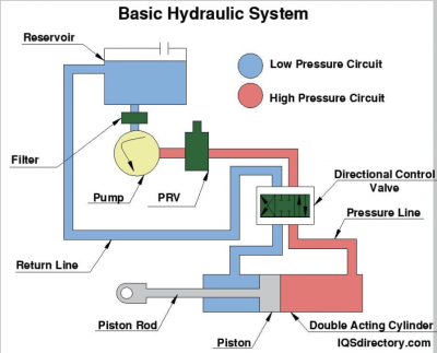
The definition of hydraulics is the mechanical study of fluids, which have the ability to perform complicated work. When you apply pressure to a liquid in a confined space, the pressure is applied equally to all parts of the space. A hydraulic system is capable of multiplying the force created by the pressure. This simple principle enables people to lift thousands of pounds by using a very small amount of force. Part of what defines a hydraulic is the type of fluid it uses, which is determined by its viscosity. In most hydraulic systems, the fluid has a low viscosity that ensures an easy flow to perform the needed work.
Three of the types of hydraulic systems are gear pumps, screw pumps, and fixed placement vane pumps. As a rotor moves around the housing, the vanes adjust the tips of the vanes touching the inner surface of the housing. The fluid enters the housing and is discharged as the vane and rotor turn. Rotary vane pumps operate best with a low viscosity fluid.
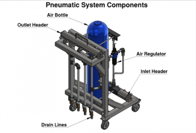
Pneumatic systems use compressed air to move solid objects through a system of tubes. They initially came into use at the end of the 19th Century and became very popular during the 20th Century. In the middle of the 20th Century they were a method of making purchases at retail outlets where the customer’s bill and money were sent to a central location. This form of use can still be seen at drive up banks. Air brakes are a form of pneumatic using compressed air for a form of friction brake, which begins by the activation of a piston that applies pressure on brake pads. Exercise machines use the resistant factor of a pneumatic cylinder that can be adjusted to fit the user. Pneumatic motors where compressed air is converted to mechanical energy by a linear motion. It is ideal for moving dry bulk materials as well as being cost effective. Feeds or grain are dumped into a high velocity gas stream using a rotary airlock valve where it is carried through pipes. This method is widely used as a conveying system for grain and cereal production. Dense-phase pneumatics has a line pressure calibrated to match the characteristics of the material being moved allowing solid material to transform into a liquid state when being moved at a slower velocity.
STEAM TURBINE
Basic Theory
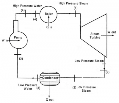
The steam turbine is one kind of heat engine machine in which steam's heat energy is converted to mechanical work.The construction of steam turbine is very simple.There is no piston rod,flywheel or slide valves attached to the turbine.So maintenance is quite easy.It consists of a rotor and a set of rotating blades which are attached to a shaft and the shaft is placed in the middle of the rotor.An electric generator known as steam turbine generator is connected to the rotor shaft.The turbine generator collects the mechanical energy from the shaft and converts it into electrical energy.Steam turbine generator also improves the turbine efficiency.
Working Principle
Working principle of steam turbine depends on the dynamic action of steam.A high-velocity steam is coming from the nozzles and it strikes the rotating blades which are fitted on a disc mounted on a shaft.This high-velocity steam produces dynamic pressure on the blades in which blades and shaft both start to rotate in the same direction. Basically,in a steam turbine pressure energy of steam extracts and then it converted into kinetic energy by allowing the steam to flow through thew nozzles.The conversion of kinetic energy does mechanical work to the rotor blades and the rotor is connected to a steam turbine generator which acts as a mediator.Turbine generator collects mechanical energy from the rotor and converts into electrical energy.Since the construction of steam turbine is simple, its vibration is much less than the other engine for same rotating speed.Though different types of governing system are used to improve turbine speed.
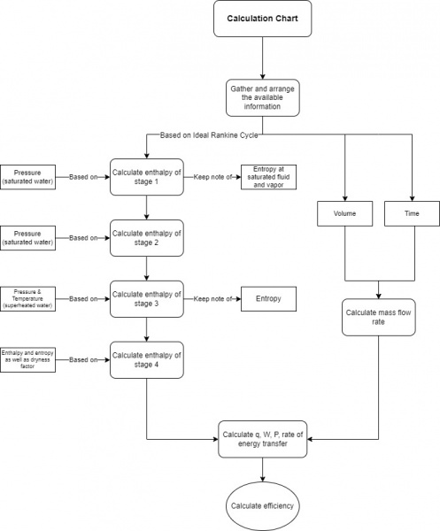
Experiment Calculation
- Volume = 400 ml
- Time = 8,67 s
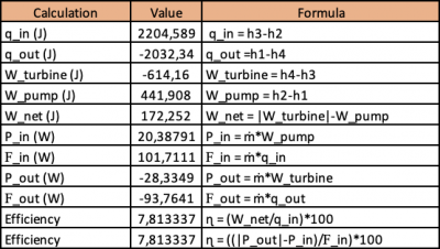
The first table shows various of enthalpies based on pressure and time value

The second table shows the initial volume and time needed followed by the mass flow rate and pressure

The third table shows the output such as heat, work, power, energy transfer, and efficiency.
Flowchart
Conclusion
From this experiment of steam turbine, we got the output of power (input and output):
- 20,38791 W
- -28,3349 W
And the efficiency of this experiment both calculation of insulting power and heat is:
- 7,81337 %
This system is noteworthy enough while converting turbocharger to steam turbine generator. with conscious thinking we realized that we can evaluate what is the shortcoming of this experiment and we are desire to reevaluate to have a better output of this experiment of steam turbine generator.
For furthermore explanation, you can check my youtube video about my report : https://www.youtube.com/watch?v=67FYKoOPZ1Y
Conscious Effort
From this experiment, I learned a lot that we must be patient and receive all the good or bad things that happened. Many trial and error occured in this experiment calculation and my eagerness to finish this experiment strong does not let the demon to incite me giving up on the miscalculation. Consciousness is a big part from this experiment. Always stay conscious. I am My Consciousness
Semester Final Reflection
Thank God I was able to finish this semester smoothly and well. In this ECS course I have implemented consciousness in all aspects. There are many theories from various materials that contain a lot of content. With consciousness I can study it well even though I have many shortcomings in understanding everything. With self-reflection, I understand and am sincere about my learning abilities and the tasks I have done. Alhamdulillah, I was given the blessing of gratitude to study well and have finished it. I am My Consciousness!!


