Difference between revisions of "Muhammad Ryan Rafi'uddin"
| (37 intermediate revisions by the same user not shown) | |||
| Line 1: | Line 1: | ||
| − | |||
| − | |||
| + | == Introduction== | ||
| + | My name is Muhammad Ryan Rafi'uddin with student number 2006488133 currently majoring in Mechanical Engineering. | ||
| + | |||
| + | == Relation Between Industries == | ||
Below is my short conversation regarding the relation between sugar cane factory, automotive factory and oil and gas company with chatGPT | Below is my short conversation regarding the relation between sugar cane factory, automotive factory and oil and gas company with chatGPT | ||
Connection between energy industries | Connection between energy industries | ||
| − | Ryan: what is the relation between sugar cane factory, automotive factory and oil and gas company? | + | '''Ryan''': what is the relation between sugar cane factory, automotive factory and oil and gas company? |
| − | ChatGPT: At first glance, there may not seem to be a direct relationship between a sugar cane factory, an automotive factory, and an oil and gas company, as they are all in different industries. However, there are some potential connections between them: | + | '''ChatGPT''': At first glance, there may not seem to be a direct relationship between a sugar cane factory, an automotive factory, and an oil and gas company, as they are all in different industries. However, there are some potential connections between them: |
Energy usage: All three industries are heavy users of energy. A sugar cane factory requires energy to power the machinery that processes the cane into sugar or ethanol. An automotive factory requires energy to power the assembly line and machinery used to manufacture cars. An oil and gas company requires energy to extract, refine, and transport oil and gas. In each case, the companies may be interested in finding ways to reduce their energy consumption or transition to more sustainable energy sources. | Energy usage: All three industries are heavy users of energy. A sugar cane factory requires energy to power the machinery that processes the cane into sugar or ethanol. An automotive factory requires energy to power the assembly line and machinery used to manufacture cars. An oil and gas company requires energy to extract, refine, and transport oil and gas. In each case, the companies may be interested in finding ways to reduce their energy consumption or transition to more sustainable energy sources. | ||
| Line 18: | Line 20: | ||
Overall, while these industries may not have a direct relationship, there are potential connections between them through their use of energy, transportation needs, and production of co-products. | Overall, while these industries may not have a direct relationship, there are potential connections between them through their use of energy, transportation needs, and production of co-products. | ||
| + | == Individual Project == | ||
| + | For this class's individual project, I would like to choose IC engine as the topic of the individual project. I would like to do research regarding the effect of different types of variable valve timing on the engine's efficiency and performance. | ||
| + | |||
| + | '''Introduction''' | ||
| + | |||
| + | In order for the Internal Combustion engine to work properly, the camshaft needs to open the intake and exhaust valves at a specific set of time so that the fuel and air can be drawn in and the burnt fuel can get out at the proper time. The precise timing of the closing and the opening of the valves corresponds to the engine’s position is known as valve timing. An engine needs to draw in more air-fuel mixture to produce more power when the engine runs at high speed, thus, the inlet valves need to be opened earlier and for a longer time. In older, more conventional engines, the period when the valves are open was optimized only for a single speed. Thus, when the engine speed increases the engine suffers from a deficiency due to power loss. Variable valve timing is developed to overcome such deficiency by diversifying the timing of the intake and exhaust valves opening for various engine speeds. | ||
| + | |||
| + | '''Studies and Findings''' | ||
| + | |||
| + | The following experiment is conducted by Jonas Suhardi on Honda CR-V engine with i-VTEC. | ||
| + | |||
| + | [[File:torquevvt.jpg|800px]] | ||
| + | |||
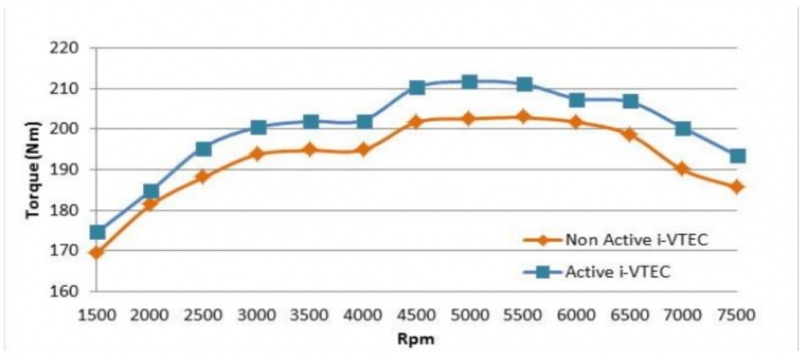
| + | With an active i-VTEC engine, the peak torque produced is 211.7 Nm at 4900 RPM while for a non-active i-VTEC is 202.8 5350 Rpm. The torques produced by an active i-vtec system are greater than those produced by a non-active i-vtec system on both low and high rotation. The mean average value of torque produced by active i-VTEC system is 200.03, while for non-active i-VTEC system is 192.69. Torque produced by an active i-VTEC system is 3.67% higher than non-active i-VTEC engine. | ||
| + | |||
| + | [[File:powervvt.jpg|800px]] | ||
| + | |||
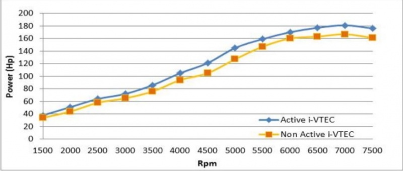
| + | With the active i-VTEC system the highest power generated is 181.5 HP at 6910 RPM, while for the non active i-VTEC system is 167.7 HP at 7020 RPM. The power generated by the active i-VTEC system is greater than those generated by the non active i-VTEC system on both low and high RPMs. The mean average value of power generated by the active i-VTEC system is 118.85 HP, while for the non active i-VTEC system is 107.75 HP. Power generated by the active i-VTEC system is 9.33% higher than the non active i-VTEC system. | ||
| + | |||
| + | From experiments above, it can be concluded that engines with VVT systems produce more torque and power than engines with non-active VVT system, even though the change is not that significant. | ||
| + | |||
| + | ==Internal Combustion Engine Simulation == | ||
| + | [[File:ICEmodelingryan2.jpg]] | ||
| + | |||
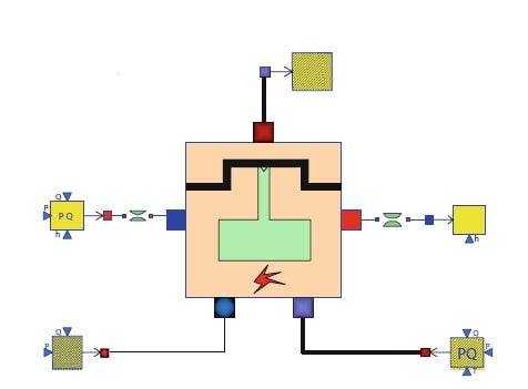
| + | Today's class topic is about learning how to create a simulation of an ICE engine using OpenModelica. Below is my understanding regarding today's topic: | ||
| + | The first step is to install ThermoSysPro to OpenModelica by importing the ThermoSysPro library to OpenModelica. The next step is to create a new OM class and then drag the IC engine from the ThermoSysPro library into the new OM class. Drag FuelSourcePQ from the library and connect it to the gas of IC engine to simulate the fuel. Drag one SourcePQ for flue gases to the model and add another type of SourcePQ for water/steam. Add one Sink to the outlet part of IC engine for flue gases and add another type of Sink for water/steam. The last step is to input the variables into the parameters. | ||
| + | |||
| + | |||
| + | == Summary of 07/03/2023 Class == | ||
| + | |||
| + | Desalination is the process of purifying seawater by removing its salt content and other minerals to make it safe for drinking or for industrial purposes. This process can be carried out with several methods, but the most common ones include Reverse Osmosis, Distillation, and Electrodialysis. Compared to other sources of fresh water, desalination has a number of benefits. In locations with a shortage of fresh water, it offers a dependable source of water and can lessen the strain on the available freshwater resources. Moreover, it can be used to supply water for commercial and industrial uses, which can assist economic growth in arid areas. Desalination, however, also has certain drawbacks. It is a procedure that uses a lot of energy, which could raise greenhouse gas emissions and exacerbate climate change. Desalination infrastructure may be complex for low-income areas to access since it is costly to construct and maintain. Desalination plants also release numerous amounts of carbon dioxide into the environment. To overcome this, the technology of carbon capture utilization and storage can be applied to the desalination process to recover the wasted carbon dioxide that is released into the air. | ||
| + | |||
| + | Slides: https://www.canva.com/design/DAFcv1vNrxU/l0feI0oudLlxid21euo81g/view?utm_content=DAFcv1vNrxU&utm_campaign=designshare&utm_medium=link2&utm_source=sharebutton | ||
| + | |||
| + | |||
| + | == Personal Project == | ||
| + | |||
| + | I have decided to change my personal project topic to hydro fuel. This project will observe the power output that is generated by a hydro fuel-powered generator with varying parameters of plate type, thickness, and dimension. I chose Aluminum A1100 with a thickness of 4 millimeters and a dimension of 15 x 10 centimeters as the plate material for this project. I have sheared a large aluminum plate into much smaller pieces, below is the video: | ||
| + | |||
| + | https://youtu.be/bz1g27ZlMvg | ||
| + | |||
| + | '''Hydrogen Hydrolysis Generator Experiment''' | ||
| + | |||
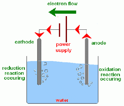
| + | Last week at Rasendriya's house, my classmates and I conducted an experiment regarding the Hydrogen generator. The working principle of the generator itself is when an electrical current of certain amperes passes through the electrolyte solution, a chemical reaction occurs the at the electrodes, causing the water molecules at the anode to be oxidized to produce oxygen and positively charged hydrogen ions, meanwhile at the cathode, the hydrogen ions combine with electrons from the electrical current to produce hydrogen gas. | ||
| + | |||
| + | [[File:Electrolysisryan.gif|400px]] | ||
| + | |||
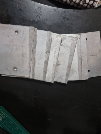
| + | For this experiment, I chose 8 Plates of Aluminum A1100 4mm x 15 cm x 10 cm as the electrodes. | ||
| + | |||
| + | [[File:Aluminumryan.jpg|400px]] | ||
| + | |||
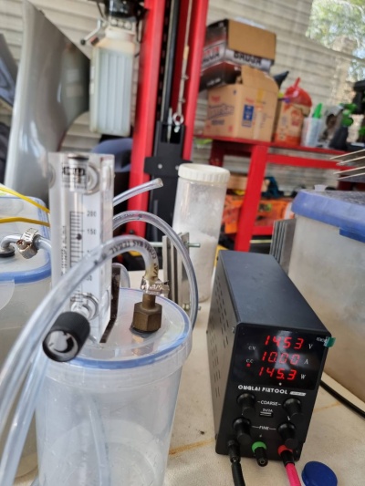
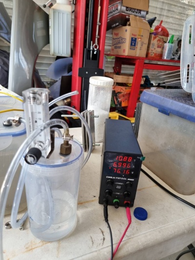
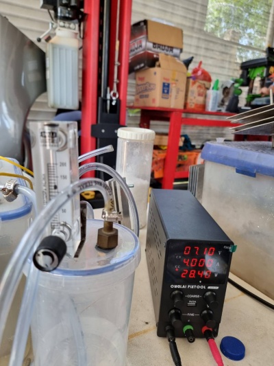
| + | From the experiment, can be obtained the rate of hydrogen produced per minute, the result can be seen below; | ||
| + | |||
| + | [[File:Result 1ryan.jpg|400px]] | ||
| + | Current: 10 Amperes, Rate: 140 ml/min | ||
| + | |||
| + | [[File:Result 2ryan.jpg|400px]] | ||
| + | Current: 7 Amperes, Rate: 130 ml/min | ||
| + | |||
| + | [[File:Result 3ryan.jpg|400px]] | ||
| + | Current: 4 Amperes, Rate: 120 ml/min | ||
| + | |||
| + | Below is the PPT link for the Midterm presentation: | ||
| + | |||
| + | https://docs.google.com/presentation/d/1vtPhbgDKJkx1xpnfRP_aKEDcBJ-_4kiNTeLTk_DrQSg/edit#slide=id.g22c8171bd39_0_56 | ||
| − | |||
| − | + | == Final Project == | |
| + | https://docs.google.com/document/d/1EU5rDiybHB5FdPVD2WlhUIP_4JotXiNcu4G9mKXMXDY/edit?usp=sharing (docx link) | ||
| + | https://docs.google.com/presentation/d/1vtPhbgDKJkx1xpnfRP_aKEDcBJ-_4kiNTeLTk_DrQSg/edit?usp=sharing (pptx link) | ||
Latest revision as of 10:47, 13 June 2023
Contents
Introduction
My name is Muhammad Ryan Rafi'uddin with student number 2006488133 currently majoring in Mechanical Engineering.
Relation Between Industries
Below is my short conversation regarding the relation between sugar cane factory, automotive factory and oil and gas company with chatGPT
Connection between energy industries
Ryan: what is the relation between sugar cane factory, automotive factory and oil and gas company?
ChatGPT: At first glance, there may not seem to be a direct relationship between a sugar cane factory, an automotive factory, and an oil and gas company, as they are all in different industries. However, there are some potential connections between them:
Energy usage: All three industries are heavy users of energy. A sugar cane factory requires energy to power the machinery that processes the cane into sugar or ethanol. An automotive factory requires energy to power the assembly line and machinery used to manufacture cars. An oil and gas company requires energy to extract, refine, and transport oil and gas. In each case, the companies may be interested in finding ways to reduce their energy consumption or transition to more sustainable energy sources.
Transportation: Both the automotive and oil and gas industries are heavily involved in transportation. The automotive industry manufactures cars and trucks that run on gasoline or diesel fuel, which is produced by the oil and gas industry. Additionally, both industries rely on transportation infrastructure to move goods and people from one place to another.
Co-products: Sugar cane factories and oil and gas companies may have a connection through the production of ethanol. Sugar cane can be processed into ethanol, which is used as a biofuel in some areas. Oil and gas companies may also produce ethanol as a co-product during the refining of crude oil.
Overall, while these industries may not have a direct relationship, there are potential connections between them through their use of energy, transportation needs, and production of co-products.
Individual Project
For this class's individual project, I would like to choose IC engine as the topic of the individual project. I would like to do research regarding the effect of different types of variable valve timing on the engine's efficiency and performance.
Introduction
In order for the Internal Combustion engine to work properly, the camshaft needs to open the intake and exhaust valves at a specific set of time so that the fuel and air can be drawn in and the burnt fuel can get out at the proper time. The precise timing of the closing and the opening of the valves corresponds to the engine’s position is known as valve timing. An engine needs to draw in more air-fuel mixture to produce more power when the engine runs at high speed, thus, the inlet valves need to be opened earlier and for a longer time. In older, more conventional engines, the period when the valves are open was optimized only for a single speed. Thus, when the engine speed increases the engine suffers from a deficiency due to power loss. Variable valve timing is developed to overcome such deficiency by diversifying the timing of the intake and exhaust valves opening for various engine speeds.
Studies and Findings
The following experiment is conducted by Jonas Suhardi on Honda CR-V engine with i-VTEC.
With an active i-VTEC engine, the peak torque produced is 211.7 Nm at 4900 RPM while for a non-active i-VTEC is 202.8 5350 Rpm. The torques produced by an active i-vtec system are greater than those produced by a non-active i-vtec system on both low and high rotation. The mean average value of torque produced by active i-VTEC system is 200.03, while for non-active i-VTEC system is 192.69. Torque produced by an active i-VTEC system is 3.67% higher than non-active i-VTEC engine.
With the active i-VTEC system the highest power generated is 181.5 HP at 6910 RPM, while for the non active i-VTEC system is 167.7 HP at 7020 RPM. The power generated by the active i-VTEC system is greater than those generated by the non active i-VTEC system on both low and high RPMs. The mean average value of power generated by the active i-VTEC system is 118.85 HP, while for the non active i-VTEC system is 107.75 HP. Power generated by the active i-VTEC system is 9.33% higher than the non active i-VTEC system.
From experiments above, it can be concluded that engines with VVT systems produce more torque and power than engines with non-active VVT system, even though the change is not that significant.
Internal Combustion Engine Simulation
Today's class topic is about learning how to create a simulation of an ICE engine using OpenModelica. Below is my understanding regarding today's topic: The first step is to install ThermoSysPro to OpenModelica by importing the ThermoSysPro library to OpenModelica. The next step is to create a new OM class and then drag the IC engine from the ThermoSysPro library into the new OM class. Drag FuelSourcePQ from the library and connect it to the gas of IC engine to simulate the fuel. Drag one SourcePQ for flue gases to the model and add another type of SourcePQ for water/steam. Add one Sink to the outlet part of IC engine for flue gases and add another type of Sink for water/steam. The last step is to input the variables into the parameters.
Summary of 07/03/2023 Class
Desalination is the process of purifying seawater by removing its salt content and other minerals to make it safe for drinking or for industrial purposes. This process can be carried out with several methods, but the most common ones include Reverse Osmosis, Distillation, and Electrodialysis. Compared to other sources of fresh water, desalination has a number of benefits. In locations with a shortage of fresh water, it offers a dependable source of water and can lessen the strain on the available freshwater resources. Moreover, it can be used to supply water for commercial and industrial uses, which can assist economic growth in arid areas. Desalination, however, also has certain drawbacks. It is a procedure that uses a lot of energy, which could raise greenhouse gas emissions and exacerbate climate change. Desalination infrastructure may be complex for low-income areas to access since it is costly to construct and maintain. Desalination plants also release numerous amounts of carbon dioxide into the environment. To overcome this, the technology of carbon capture utilization and storage can be applied to the desalination process to recover the wasted carbon dioxide that is released into the air.
Personal Project
I have decided to change my personal project topic to hydro fuel. This project will observe the power output that is generated by a hydro fuel-powered generator with varying parameters of plate type, thickness, and dimension. I chose Aluminum A1100 with a thickness of 4 millimeters and a dimension of 15 x 10 centimeters as the plate material for this project. I have sheared a large aluminum plate into much smaller pieces, below is the video:
Hydrogen Hydrolysis Generator Experiment
Last week at Rasendriya's house, my classmates and I conducted an experiment regarding the Hydrogen generator. The working principle of the generator itself is when an electrical current of certain amperes passes through the electrolyte solution, a chemical reaction occurs the at the electrodes, causing the water molecules at the anode to be oxidized to produce oxygen and positively charged hydrogen ions, meanwhile at the cathode, the hydrogen ions combine with electrons from the electrical current to produce hydrogen gas.
For this experiment, I chose 8 Plates of Aluminum A1100 4mm x 15 cm x 10 cm as the electrodes.
From the experiment, can be obtained the rate of hydrogen produced per minute, the result can be seen below;
Current: 10 Amperes, Rate: 140 ml/min
Current: 7 Amperes, Rate: 130 ml/min
Current: 4 Amperes, Rate: 120 ml/min
Below is the PPT link for the Midterm presentation:
Final Project
https://docs.google.com/document/d/1EU5rDiybHB5FdPVD2WlhUIP_4JotXiNcu4G9mKXMXDY/edit?usp=sharing (docx link) https://docs.google.com/presentation/d/1vtPhbgDKJkx1xpnfRP_aKEDcBJ-_4kiNTeLTk_DrQSg/edit?usp=sharing (pptx link)
