Difference between revisions of "Rafid Fawwaz Fadhal"
Rafid.fawwaz (talk | contribs) (→Pertemuan 3 (02/03/2021)) |
Rafid.fawwaz (talk | contribs) (→Pertemuan 5 (10/03/2021)) |
||
| (15 intermediate revisions by the same user not shown) | |||
| Line 56: | Line 56: | ||
3. The example combined cycle power plant will be shown and we can make that as our guide to make the cycle and choose the "tools/Elements" to make the cycle from the library. Move the cursor into the elements and hold it shows up a label contain library sources. | 3. The example combined cycle power plant will be shown and we can make that as our guide to make the cycle and choose the "tools/Elements" to make the cycle from the library. Move the cursor into the elements and hold it shows up a label contain library sources. | ||
| − | [[File:Melihat_Library.png|1| | + | [[File:Melihat_Library.png|1|400px|center|]] |
4. File -> New Modelica Class | 4. File -> New Modelica Class | ||
| Line 66: | Line 66: | ||
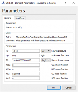
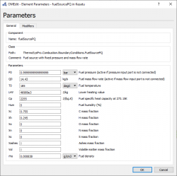
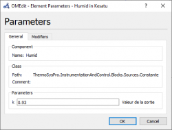
6. We can adjust each parameter independently of the input, output, valve, etc such as Gas Rampe, Humid, Fuel source, Flue Gas Source, Water/steam source, Generator efficiency, etc. Moreover, we can also set the unit of every parameters. | 6. We can adjust each parameter independently of the input, output, valve, etc such as Gas Rampe, Humid, Fuel source, Flue Gas Source, Water/steam source, Generator efficiency, etc. Moreover, we can also set the unit of every parameters. | ||
| − | [[File:Parameter_Flue_Gas.png|1| | + | [[File:Parameter_Flue_Gas.png|1|250px|center|]] |
| − | [[File:Parameter_Fuel_.png|1| | + | [[File:Parameter_Fuel_.png|1|250px|center|]] |
| − | [[File:Parameter_Humid.png|1| | + | [[File:Parameter_Humid.png|1|250px|center|]] |
7. Finally, the cycle can start to be simulated by click the "Green Arrow" button | 7. Finally, the cycle can start to be simulated by click the "Green Arrow" button | ||
| Line 78: | Line 78: | ||
[[File:Final_Result_Test.png|1|600px|center|]] | [[File:Final_Result_Test.png|1|600px|center|]] | ||
| − | === Pertemuan 3 ( | + | === Pertemuan 3 (03/03/2021) === |
Pada pertemuan ini, hal pertama yang dibahas adalah makna sistem secara umum dan pada energy conservation. Sistem adalah kumpulan elemen yang saling berhubungan dan terintegrasi dalam menjalankan suatu proses untuk mencapai satu tujuan. Contoh sistem yang paling umum adalah sistem pencernaan dan sistem organ reproduksi. Pada sistem reproduksi, setiap organ memiliki fungsi nya masing-masing dalam rangka mencapai tujuan aktivitas biologis manusia dan menghasilkan janin. | Pada pertemuan ini, hal pertama yang dibahas adalah makna sistem secara umum dan pada energy conservation. Sistem adalah kumpulan elemen yang saling berhubungan dan terintegrasi dalam menjalankan suatu proses untuk mencapai satu tujuan. Contoh sistem yang paling umum adalah sistem pencernaan dan sistem organ reproduksi. Pada sistem reproduksi, setiap organ memiliki fungsi nya masing-masing dalam rangka mencapai tujuan aktivitas biologis manusia dan menghasilkan janin. | ||
| Line 85: | Line 85: | ||
[[File:Rumus_Pressure.jpg|1|400px|center|]] [[File:Rumus_Pressure_2.png|1|300px|center|]] [[File:Konservasi_Energi.png|1|200px|center|]] | [[File:Rumus_Pressure.jpg|1|400px|center|]] [[File:Rumus_Pressure_2.png|1|300px|center|]] [[File:Konservasi_Energi.png|1|200px|center|]] | ||
| + | |||
| + | === Pertemuan 4 (04/03/2021) === | ||
| + | |||
| + | Gas Turbine Flow Chart Proses : | ||
| + | |||
| + | 1. Compressor take in/suck in the fresh air from the environment | ||
| + | |||
| + | 2. A Compressor compresses air to a higher temperature and pressure. Since the higher pressure is directly proportional with the temperature | ||
| + | |||
| + | 3. Fuel and pressurize air from compressor are sent to the combustion chamber, where fuel is burned at constant pressure. The resulting hot gasses output are sent to the turbine to move it. | ||
| + | |||
| + | 4. The high temperature gasses expand to the ambient pressure in the turbine. The output energy from the moving turbine will be used to move the compressor and move the generator to produce electricity. | ||
| + | |||
| + | [[File:Ideal_Brayton_Cycle.png|1|250px|center|]] | ||
| + | |||
| + | There are several keywords that are very related with the brayton cycle graph : | ||
| + | |||
| + | A. Isentropic Process: It is a thermodynamic process in which the entropy of the system remains unchanged (i.e. entropy remains constant). There is no dissipation of heat takes process or called as reversible adiabatic process. | ||
| + | |||
| + | B. Isochoric Process: The process which takes place at constant volume or called isometric process | ||
| + | |||
| + | C. Entropy is a measure of the energy dispersal in the system. Entropy is a measure of randomness or disorder of the system. The greater the randomness, the higher the entropy. The unit is; joules per kelvin (J⋅K−1) | ||
| + | |||
| + | D.Enthalpy is a thermodynamic property of a system. It is the sum of the internal energy added to the product of the pressure and volume of the system that reflects the capacity to release heat. Enthalpy formula; H = E + PV (where H is enthalpy, E is internal energy of the system, P is pressure, and V is volume) | ||
| + | |||
| + | E. Combustion is the substance reaction between oxygen from the air and the fuel that generate heat and light in the form of flame. | ||
| + | |||
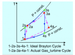
| + | Brayton cycle process/graphs explanation : | ||
| + | |||
| + | Process 1-2 | ||
| + | |||
| + | It is isentropic compression process. In this section, there are a little rise in the temperature of gas occurs due to compression. Since it is a compression process, volume of the gas decreases. | ||
| + | |||
| + | Process 2-3 | ||
| + | |||
| + | It is isobaric heat addition process. A little increase in volume happens due to heat addition. Since it is a heat addition process, temperature of the gas increases. In this step, the graph reach the highest temperature, but the temperature is constant. | ||
| + | |||
| + | Process 3-4 | ||
| + | |||
| + | It is isentropic expansion process. There is little dip in temperature occurs due to expansion. Since it is an expansion process, volume of the gas increases | ||
| + | |||
| + | Process 4-1 | ||
| + | |||
| + | It is isobaric heat rejection process. A little decrease in volume happens due to heat rejection. Since it is a heat rejection process, temperature of the gas decreases. | ||
| + | |||
| + | Note : In the actual Brayton cycle process compared to the gas turbine cyle, there will be a slightly different due to the compressor consumes more work (efficiency). However, the turbine produce less works than the actual brayton cycle. | ||
| + | |||
| + | Source : | ||
| + | |||
| + | https://ecourses.ou.edu/cgi-bin/ebook.cgi?doc&topic=th&chap_sec=09.1&page=theory | ||
| + | https://clubtechnical.com/brayton-cycle | ||
| + | |||
| + | [[File:Brayton_Diagram.png|1|400px|center|]] | ||
| + | |||
| + | [[File:Comparation_Cycle.png|1|250px|center|]] | ||
| + | |||
| + | |||
| + | === Homework 2 (04/03/2021) === | ||
| + | |||
| + | A. Compressor | ||
| + | |||
| + | Compressor in gas turbine has a function to collect air into the engine, then pressurizes it and finally send it to the combustion chamber at very high speed. Compressor has a role to increase the pressure and temperature. | ||
| + | |||
| + | Compressor energy balance equation : | ||
| + | |||
| + | |||
| + | '''Win + m.h1 = Qout + m.h2''' | ||
| + | |||
| + | W in = Rate of energy being transferred in to the compressor | ||
| + | |||
| + | Q out = Rate of energy being transferred out | ||
| + | |||
| + | h = enthalpy | ||
| + | |||
| + | Isentropic compressor efficiency : | ||
| + | |||
| + | [[File:Efisiensi_Kompresor.png|1|200px|]] | ||
| + | |||
| + | Compressor Power : | ||
| + | |||
| + | [[File:Power_Kompresor.png|1|200px|]] | ||
| + | |||
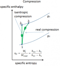
| + | Below are h vs s graph of the actual vs isentropic processes of an adiabatic compressor | ||
| + | |||
| + | [[File:Isentropic_Compression.png|1|200px|center|]] | ||
| + | |||
| + | === Pertemuan 5 (10/03/2021) === | ||
| + | |||
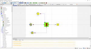
| + | Pada pertemuan kelima ini, kita melakukan simulasi dengan open modelica berdasarkan parameter dan skema yang sudah tersedia. Kita membuat sebuah skema dengan "Combustion Chamber" sebagai Part utama serta 3 part input ("Source PQ (Water Steam)", "Source PQ (Flue Gases)", "FuelSourcePQ") dan 1 buah part output yaitu "Sink (Flue Gasses)". Semua part tersebut disambungkan dengan connector dan di berikan masukan parameter tersendiri. | ||
| + | |||
| + | Berikut skema yang kami buat : | ||
| + | |||
| + | [[File:Simulasi_Kelas.png|1|300px|center|]] | ||
| + | |||
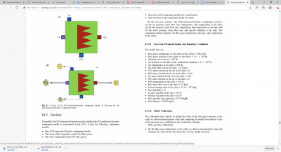
| + | Berikut daftar parameter yang kami berikan/Input : | ||
| + | |||
| + | [[File:Parameter_Simulasi1.png|1|400px|center|]] | ||
| + | |||
| + | Kemudian kami melakukan simulasi (simulate), dan menghasilkan hasil yang sesuai dengan daftar parameter yang diketahui : | ||
| + | |||
| + | [[File:Hasil_Simulasi1.png|1|400px|center|]] | ||
| + | |||
| + | === Homework 3 (10/03/2021) === | ||
| + | |||
| + | We are given a homework to input a random variation on the parameter and see the effect/results in the sink part | ||
| + | |||
| + | 1. In the first case, i decide to increase several value of parameter | ||
| + | |||
| + | Source PQ (Water Steam) | ||
| + | |||
| + | P0 = 10 bar | ||
| + | |||
| + | Source PQ (Flue Gases) | ||
| + | |||
| + | P0 = 20 bar | ||
| + | |||
| + | Q0 = 600 kg/s | ||
| + | |||
| + | T0 = 500 deg/C | ||
| + | |||
| + | Fuel Source PQ | ||
| + | |||
| + | Q0 = 20 kg/s | ||
| + | |||
| + | To = 300 deg/C | ||
| + | |||
| + | And below is the result from the simulation | ||
| + | |||
| + | [[File:Hasil_Simulasi_Up.png|1|150px|center|]] | ||
| + | |||
| + | 2. In the second case, i decide to decrease several value of parameter | ||
| + | |||
| + | Source PQ (Water Steam) | ||
| + | |||
| + | P0 = 2 bar | ||
| + | |||
| + | Source PQ (Flue Gases) | ||
| + | |||
| + | P0 = 10 bar | ||
| + | |||
| + | Q0 = 300 kg/s | ||
| + | |||
| + | T0 = 250 deg/C | ||
| + | |||
| + | Fuel Source PQ | ||
| + | |||
| + | Q0 = 5 kg/s | ||
| + | |||
| + | To = 110 deg/C | ||
| + | |||
| + | And below is the result from the simulation | ||
| + | |||
| + | [[File:Hasil_Simulasi_Down.png|1|150px|center|]] | ||
Latest revision as of 16:07, 10 March 2021
Contents
Biodata
Nama Lengkap : Rafid Fawwaz Fadhal
Nama Panggilan : Rafid
NPM : 1806187682
Tempat, tanggal lahir : Tangerang, 5 Agustus 2001
Saya adalah mahasiswa teknik mesin KKI UI 2018 DI Universitas Indonesia. Saya memiliki harapan, agar ilmu saya dapat bermanfaat nanti untuk memajukan Indonesia tidak hanya berfokus pada bidang teknologi tetapi permasalahan mendasar lain yang memerlukan pengalaman, integritas dan niat nurani. . Hal tersebut saya jadikan pedoman dalam menjalani kuliah saat ini. Menurut saya, kemajuan Indonesia memerlukan kontribusi nyata dari para pemangku jabatan, tidak hanya sekedar teori, prediksi atau pun "katanya", tetapi berdasarkan pemantauan langsung, realita lapangan, data dan pendapat dari para ahli. Oleh karena itu, opini saya adalah teknik mata kuliah yang tepat apabila ingin kontribusi terhadap negara agar berdampak besar, tidak hanya berdasarkan ilmu pasti tetapi pengalaman berfikir, memecahkan masalah, dan lainnya. Pada kuliah ini, saya sudah mencoba dan akan memperbanyak lagi pengalaman dan hal-hal baru melalui kegiatan IKM, organisasi, panitia, student exchange, lomba dan kegiatan mengabdi sehingga suatu saat nanti apabila saya menduduki posisi penting maka saya sudah mengetahui apa masalah mendasar yang menghambat negara ini.
Pertemuan 1 (23/02/2021)
Kabar saya hari ini baik dan sehat, saya sangat antusias untuk mengikuti kelas hari ini
Note:
1. Kita harus memahami apa yang kita ketahui dan belum ketahui, sehingga memiliki rencana untuk dikembangkan
2. Arti keadilan menurut saya adalah kemampuan suatu individu atau negara dalam melakukan aktivitas tanpa memandang latar belakang dari objek tersebut.
3. Keadilan pada sisi mahasiswa fakultas teknik tidak hanya bergerak dalam pengembangan teknologi untuk membantu masyarakat tetapi mampu mengimplementasikan dan memastikan bahwa segala hal tersebut benar-benar membantu masyarakat dan memberikan dampak berkelanjutan.
4. Keadilan dapat diartikan dengan persamaan energi. Salah satu aplikasinya adalah: Pengolahan sumber daya energi dalam rangka pemenuhan energi listrik penduduk Indonesia harus mempertimbangkan kriteria alam.
5. Energi merupakan suatu yang diperlukan hal untuk melakukan usaha. Kualitas energi sangat berkaitan dengan output hasil aktivitas yang dilakukan.
Pertemuan 2 (24/02/2021)
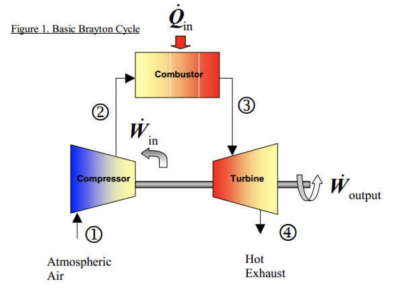
Brayton cycle is thermodynamic cycle that explain the working of some heat engines, such as turbine power cycle, generator, jet engines and helicopter motor. A simple gas turbine engine is consist of a compressor, a combuster, and a turbine. According to the principle of the Brayton cycle, air is compressed in the turbine compressor. The air is then mixed with fuel, and burned under constant pressure conditions in the combustor. The resulting hot gas is allowed to expand through a turbine to perform work. Mostly, work produced in the turbine is used to run the compressor and the rest is available to run auxiliary equipment and produce power. Combined cycle power generation improves the thermal efficiency by recovering this high temperature exhaust gas. This system is possible by adopting a waste heat recovery cycle in which exhaust gas from the gas turbine is led to the waste heat recovery boiler to generate steam using recovered heat to drive the steam turbine.
Basically, the brayton cycle consist of 4 basic process
a.) 1 -> 2 :Isentropic compression
b.) 2 -> 3 :Reversible constant pressure heat addition
c.) 3 -> 4 :Isentropic expansion
d.) 4 -> 5 :Reversible constant pressure heat rejection (exhaust and intake in the open cycle)
In this class, we will use open modelica apps. Open modelica is an open source modeling language for modeling, analyzing, simulating and optimizing complex dynamic system and cycle. Based on the "Pertemnuan 2" Homework, i was instructed to try simulating and learn the basic tools of open modelica from other source (Youtube ,etc), so that in this section i will explain how to simulate the single system cycle.
1. Firstly, we open the open modelica. Then click system "libraries" and choose "Thermosyspro"
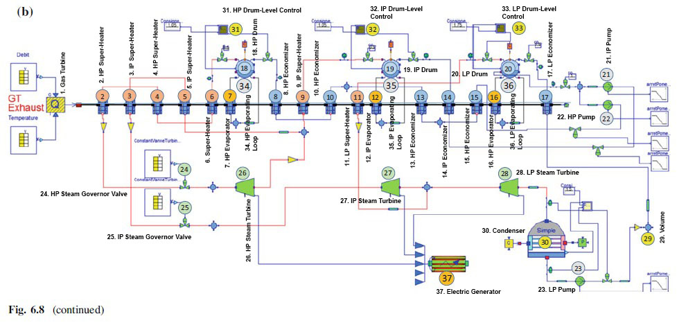
2. After it's open in the side right interface, Click Examples -> CombinedCyclePowerPlant -> CombinedCycle_Load_100_50
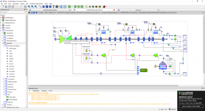
3. The example combined cycle power plant will be shown and we can make that as our guide to make the cycle and choose the "tools/Elements" to make the cycle from the library. Move the cursor into the elements and hold it shows up a label contain library sources.
4. File -> New Modelica Class
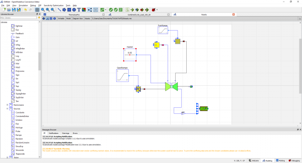
5. Starts making the schematic. (Note : A. Use unusual file name in bahasa to prevent error. B. Connect the line exactly in the junction.)
6. We can adjust each parameter independently of the input, output, valve, etc such as Gas Rampe, Humid, Fuel source, Flue Gas Source, Water/steam source, Generator efficiency, etc. Moreover, we can also set the unit of every parameters.
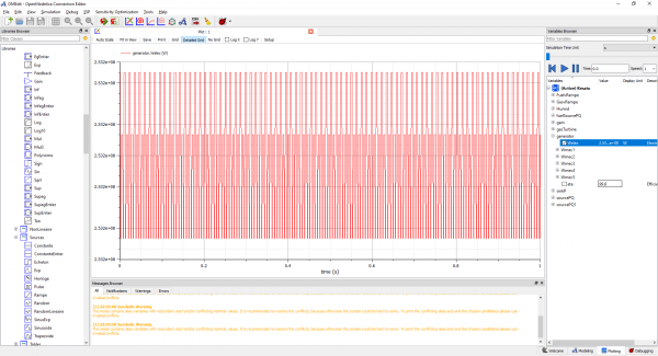
7. Finally, the cycle can start to be simulated by click the "Green Arrow" button
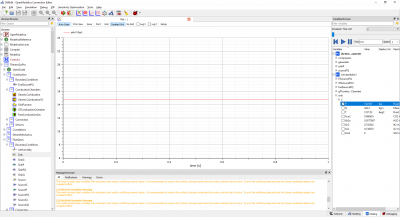
8. The final result will shown as a graph and outcome detailed data of several parameters. (Note : Click variables in the right side interface, the choose generator -> Checklist welec.)
Pertemuan 3 (03/03/2021)
Pada pertemuan ini, hal pertama yang dibahas adalah makna sistem secara umum dan pada energy conservation. Sistem adalah kumpulan elemen yang saling berhubungan dan terintegrasi dalam menjalankan suatu proses untuk mencapai satu tujuan. Contoh sistem yang paling umum adalah sistem pencernaan dan sistem organ reproduksi. Pada sistem reproduksi, setiap organ memiliki fungsi nya masing-masing dalam rangka mencapai tujuan aktivitas biologis manusia dan menghasilkan janin.
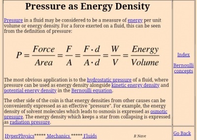
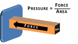
Kemudian hal penting berikutnya adalah arti dari konservasi energi. Yang saya pahami dari konservasi energi berdasarkan opini teman-teman saya adalah konservasi energi memiliki arti bahwa energi tidak dapat dimusnahkan tetapi dapat diubah bentuk, contohnya adalah gerakan turbin pada kincir angin dapat ditransformasikan menjadi listrik. Hal ini membuktikan bahwa jumlah energi tersebut tetap ada tetapi berubah bentuk/wujud. Disisi lain, agar dapat menjaga jumlah energi yang di transformasikan dibutuhkan teknik pengolahan dan penggunaan energi yang efisien dan rasional sehingga energi dapat terpakai secara maksimal. Contoh lain adalah sistem pada open modelica berupa 2 penampungan air yang terhubung dengan pipa dan katup, sehingga dibutuhkan cara untuk menyeimbangkan air pada dua bak tersebut. Oleh karena itu, konservasi energi sangat berkaitan dengan persamaan Bernoulli dimana tekanan fluida dan kecepatan fluida saling berpengaruh. Tekanan/pressure adalah gaya/force yang tegak lurus dengan permukaan benda, sehingga tekanan sangat dipengaruhi oleh luas permukaan suatu benda. Rumus lain yang berkaitan dengan konservasi energi adalah rumus kekekalan energi mekanik yang melibatkan energi potensial dan energi kinetic.
Pertemuan 4 (04/03/2021)
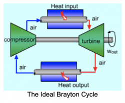
Gas Turbine Flow Chart Proses :
1. Compressor take in/suck in the fresh air from the environment
2. A Compressor compresses air to a higher temperature and pressure. Since the higher pressure is directly proportional with the temperature
3. Fuel and pressurize air from compressor are sent to the combustion chamber, where fuel is burned at constant pressure. The resulting hot gasses output are sent to the turbine to move it.
4. The high temperature gasses expand to the ambient pressure in the turbine. The output energy from the moving turbine will be used to move the compressor and move the generator to produce electricity.
There are several keywords that are very related with the brayton cycle graph :
A. Isentropic Process: It is a thermodynamic process in which the entropy of the system remains unchanged (i.e. entropy remains constant). There is no dissipation of heat takes process or called as reversible adiabatic process.
B. Isochoric Process: The process which takes place at constant volume or called isometric process
C. Entropy is a measure of the energy dispersal in the system. Entropy is a measure of randomness or disorder of the system. The greater the randomness, the higher the entropy. The unit is; joules per kelvin (J⋅K−1)
D.Enthalpy is a thermodynamic property of a system. It is the sum of the internal energy added to the product of the pressure and volume of the system that reflects the capacity to release heat. Enthalpy formula; H = E + PV (where H is enthalpy, E is internal energy of the system, P is pressure, and V is volume)
E. Combustion is the substance reaction between oxygen from the air and the fuel that generate heat and light in the form of flame.
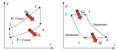
Brayton cycle process/graphs explanation :
Process 1-2
It is isentropic compression process. In this section, there are a little rise in the temperature of gas occurs due to compression. Since it is a compression process, volume of the gas decreases.
Process 2-3
It is isobaric heat addition process. A little increase in volume happens due to heat addition. Since it is a heat addition process, temperature of the gas increases. In this step, the graph reach the highest temperature, but the temperature is constant.
Process 3-4
It is isentropic expansion process. There is little dip in temperature occurs due to expansion. Since it is an expansion process, volume of the gas increases
Process 4-1
It is isobaric heat rejection process. A little decrease in volume happens due to heat rejection. Since it is a heat rejection process, temperature of the gas decreases.
Note : In the actual Brayton cycle process compared to the gas turbine cyle, there will be a slightly different due to the compressor consumes more work (efficiency). However, the turbine produce less works than the actual brayton cycle.
Source :
https://ecourses.ou.edu/cgi-bin/ebook.cgi?doc&topic=th&chap_sec=09.1&page=theory https://clubtechnical.com/brayton-cycle
Homework 2 (04/03/2021)
A. Compressor
Compressor in gas turbine has a function to collect air into the engine, then pressurizes it and finally send it to the combustion chamber at very high speed. Compressor has a role to increase the pressure and temperature.
Compressor energy balance equation :
Win + m.h1 = Qout + m.h2
W in = Rate of energy being transferred in to the compressor
Q out = Rate of energy being transferred out
h = enthalpy
Isentropic compressor efficiency :
Compressor Power :
Below are h vs s graph of the actual vs isentropic processes of an adiabatic compressor
Pertemuan 5 (10/03/2021)
Pada pertemuan kelima ini, kita melakukan simulasi dengan open modelica berdasarkan parameter dan skema yang sudah tersedia. Kita membuat sebuah skema dengan "Combustion Chamber" sebagai Part utama serta 3 part input ("Source PQ (Water Steam)", "Source PQ (Flue Gases)", "FuelSourcePQ") dan 1 buah part output yaitu "Sink (Flue Gasses)". Semua part tersebut disambungkan dengan connector dan di berikan masukan parameter tersendiri.
Berikut skema yang kami buat :
Berikut daftar parameter yang kami berikan/Input :
Kemudian kami melakukan simulasi (simulate), dan menghasilkan hasil yang sesuai dengan daftar parameter yang diketahui :
Homework 3 (10/03/2021)
We are given a homework to input a random variation on the parameter and see the effect/results in the sink part
1. In the first case, i decide to increase several value of parameter
Source PQ (Water Steam)
P0 = 10 bar
Source PQ (Flue Gases)
P0 = 20 bar
Q0 = 600 kg/s
T0 = 500 deg/C
Fuel Source PQ
Q0 = 20 kg/s
To = 300 deg/C
And below is the result from the simulation
2. In the second case, i decide to decrease several value of parameter
Source PQ (Water Steam)
P0 = 2 bar
Source PQ (Flue Gases)
P0 = 10 bar
Q0 = 300 kg/s
T0 = 250 deg/C
Fuel Source PQ
Q0 = 5 kg/s
To = 110 deg/C
And below is the result from the simulation

