Difference between revisions of "Osdi Osbert Billi"
(→24/02/2021 Wednesday) |
(→15/03/2021 Monday) |
||
| (42 intermediate revisions by the same user not shown) | |||
| Line 43: | Line 43: | ||
As the class ended, we are tasked in understanding OpenModelica simulator. In order to do that, we will have to watch tutorials of it. | As the class ended, we are tasked in understanding OpenModelica simulator. In order to do that, we will have to watch tutorials of it. | ||
| + | |||
| + | == 28/02/2021 Sunday == | ||
| + | |||
| + | The tutorials I found in youtube are as bellow. | ||
| + | |||
| + | <youtube width="200" height="100">SW5Eclf1tRs</youtube> | ||
| + | |||
| + | Openmodelica is a modeling language of systems containing mechanical, electrical, electronic, hydraulic, thermal, control, electric power or process-oriented subcomponents, developed by the non-profit Modelica Association. Although the languages are similar to programming languages, it focuses on a set of equations in explaining a system. In setting up a system, users won't necessarily start typing from scratch, but they can recycle subcomponents made in the libraries. | ||
| + | |||
| + | The interface consists of 4 pages on the bottom right tabs; | ||
| + | |||
| + | Welcome, where there are the the latest news and recent files windows | ||
| + | |||
| + | Modeling, where models are created | ||
| + | |||
| + | Plotting, in a graph | ||
| + | |||
| + | Debug, to correct mistakes or errors made in the models | ||
| + | |||
| + | The left corner are libraries which stores classes to build a model. The class consist of model, connectors, subcomponents, and functions. Each model have four representations; icon, diagram, text, and documentation views. | ||
| + | [[File:Icon.png|400px|thumb|left|Icon]] [[File:Diagram.png|400px|thumb|center|Diagram]] | ||
| + | |||
| + | [[File:Dfberf.png|400px|thumb|left|Text]] [[File:S).png|400px|thumb|center|Documentation]] | ||
| + | |||
| + | '''Models''' contain variables, parameters, and equations. Models can be found in each specific library to be used instead of recreating | ||
| + | |||
| + | '''Connectors''' contain flow and stream. Differences in the values of potential variables across a component are what trigger components to react. Typical examples of variables, are temperature, voltage and pressure. Differences in these quantities typically lead to dynamic behavior in the system. Flow variables normally represent the flow of some conserved quantity like mass, momentum, energy, charge, etc. These flows are usually the result of some difference in the across variables across a component model. For example, current flowing through a resistor is in response to a voltage difference across the two sides of the resistor. | ||
| + | |||
| + | After completing a model, checking would be advised to show the number of equations an variables. The simulation will run if both have the same numbers. | ||
| + | |||
| + | == 2/03/2021 Tuesday == | ||
| + | |||
| + | An example is a simple convection model | ||
| + | |||
| + | [[File:Juu.png|400px|thumb|center|Diagram of convection]] | ||
| + | |||
| + | with the following text view of each model | ||
| + | |||
| + | [[File:Dth.png|400px|thumb|left|Wall]] [[File:Fg.png|400px|thumb|center|Convection]] | ||
| + | |||
| + | [[File:Efbe.png|400px|thumb|left|Cooling]] [[File:Ghj.png|400px|thumb|center|Ambient air]] | ||
| + | |||
| + | |||
| + | |||
| + | |||
| + | In this meeting, we talked about the definition of system. To me, a system consists of components and/or elements that interacts among each other to form a unified function. A system is described from its boundaries and environment. One type of system that we are trying to understand is the energy conversion system. Understanding the system will be by analyzing the Bernoulli principle which can equate pressure in place of energy. A current of fluid can't be measured in mass. Thus, an alternative is marking a reference point of position in the fluid . That point will be used in determining the energy within. | ||
| + | |||
| + | == 6/03/2021 Saturday == | ||
| + | We are assigned to learn about the components and working principle of a gas turbine. A gas turbine is a combustion engine that generates its torsional energy from combusted. By pressurizing air, the force acted by it turns the turbine. The energy produced could be used in the form of electrical or mechanical. The basic components are compressor, combustion chamber, and the turbine. | ||
| + | |||
| + | [[File:Open-cycle-gas-turbine-figure-1.png|300px|thumb|left|Gas turbine diagram]] [[File:Th090105p.gif|1000px|thumb|center|T-s diagram]] | ||
| + | |||
| + | |||
| + | |||
| + | |||
| + | |||
| + | |||
| + | |||
| + | |||
| + | |||
| + | The air pressurized inside the gas turbine can be analyzed using the Brayton cycle to understand the thermodynamic process. The cycle can be analyzed using the T-s diagram. The ideal T-S diagram describes the property of air with adiabatic and isentropic processes, but the actual cycle are non-isentropic and non-adiabatic. This is caused by a pressure drop during heat exchanges and the change in entropy in the compressor and turbine. As air passes through the compressor, air gains heat, causing the temperature to rise slightly above the ideal temperature. The temperature rise will then cause entropy to increase. Entropy deviating from the ideal process can be expressed as isentropic efficiency. | ||
| + | |||
| + | [[File:Scrgd.png|300px|thumb|left|Isentropic efficiency]] | ||
| + | |||
| + | |||
| + | |||
| + | |||
| + | |||
| + | |||
| + | |||
| + | |||
| + | |||
| + | |||
| + | |||
| + | |||
| + | == 6/03/2021 Saturday == | ||
| + | |||
| + | Modelica provides the comfort of visioning systems, but experiments must be made to produce better results. Hence, we are tasked in defining the relationships between parameters. I'll start by analyzing the parameter change from the input to the output. Judging from these values, it can be concluded that pressure decreases, but temperature and mass flow rate increases. Next, I'll be changing each parameters P,Q and T in the air source model. | ||
| + | |||
| + | [[File:Screenshot (403).png|400px|thumb|left|Initial parameters]][[File:Screenshot (406).png|400px|thumb|center|Initial result parameters]] | ||
| + | |||
| + | |||
| + | |||
| + | |||
| + | |||
| + | |||
| + | |||
| + | |||
| + | |||
| + | |||
| + | |||
| + | |||
| + | |||
| + | |||
| + | |||
| + | |||
| + | |||
| + | |||
| + | |||
| + | |||
| + | |||
| + | |||
| + | |||
| + | |||
| + | |||
| + | |||
| + | === Source pressure === | ||
| + | I experimented on increasing the source pressure to 45 bar. The result is its influence in fluid pressure. | ||
| + | [[File:Screenshot (408).png|400px|thumb|center|Pressure change in sink]] | ||
| + | |||
| + | === Sink mass flow rate === | ||
| + | I experimented on increasing the source pressure to 320 kg/s. The result is its influence in pressure, flow rate, and temperature. | ||
| + | [[File:Screenshot (410).png|400px|thumb|center|Pressure, flow rate, and temperature change in sink]] | ||
| + | |||
| + | === Air temperature === | ||
| + | I experimented on decreasing the source pressure to 400°C. The result is its influence in pressure and temperature. | ||
| + | [[File:Screenshot (412).png|400px|thumb|center|Pressure and temperature change in sink]] | ||
| + | |||
| + | == 15/03/2021 Monday == | ||
| + | |||
| + | As an assignment this is the link to my presentation about the open gas turbine cycle. | ||
| + | |||
| + | |||
| + | <youtube width="200" height="100">pzqGvfyS2EY</youtube> | ||
Latest revision as of 13:11, 16 March 2021
Contents
Biodata
Name: Osdi Osbert Billi
NPM: 1806228026
Place and date of birth: Medan, 13th may 2000
Hobby: Watching movies
I am a student in the University of Indonesia majoring in Mechanical engineering. This is the 6th semester, and upon graduation, I hope that I could achieve my dreams to become an engineer. In this KKI program, I hope to experience new technologies that inspires.
23/02/2021 Tuesday
Today, I am good.
Today I learnt about social justice. In my opinion, justice should be unbiased, whether is for the better or worse. It should also be unbiased to a person's prestige or background. However, there are always people with defective traits or incapability. Hence, engineers should find ways to uphold social justice by designing equipment, appliances, or tools to help.
Energy can be explained as something invisible. every object has energy, but it can change as it does work. energy has the capability to do work. F=ma, which means that an action has a reaction. Derivative of work is a change of work from one state to the other and can be expressed in the equation U = Q + W, which are:
U= Change in internal energy
Q= Heat added to system
W= work (- work done by system, + work done to system)
This means that every object, system, etc. has energy that can be lost or gained.
24/02/2021 Wednesday
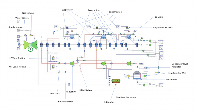
This is a diagram of a combined cycle power plant that have been labeled
As the class ended, we are tasked in understanding OpenModelica simulator. In order to do that, we will have to watch tutorials of it.
28/02/2021 Sunday
The tutorials I found in youtube are as bellow.
Openmodelica is a modeling language of systems containing mechanical, electrical, electronic, hydraulic, thermal, control, electric power or process-oriented subcomponents, developed by the non-profit Modelica Association. Although the languages are similar to programming languages, it focuses on a set of equations in explaining a system. In setting up a system, users won't necessarily start typing from scratch, but they can recycle subcomponents made in the libraries.
The interface consists of 4 pages on the bottom right tabs;
Welcome, where there are the the latest news and recent files windows
Modeling, where models are created
Plotting, in a graph
Debug, to correct mistakes or errors made in the models
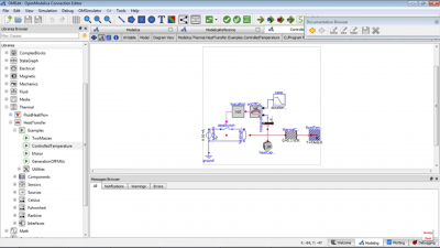
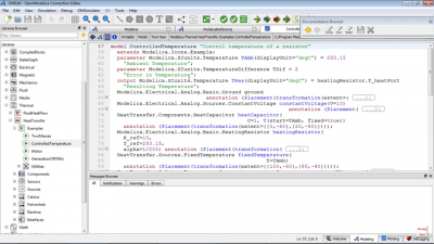
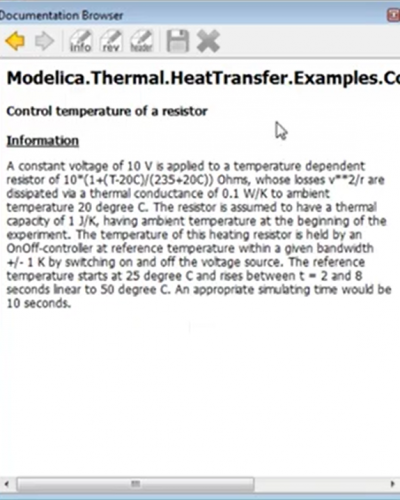
The left corner are libraries which stores classes to build a model. The class consist of model, connectors, subcomponents, and functions. Each model have four representations; icon, diagram, text, and documentation views.
Models contain variables, parameters, and equations. Models can be found in each specific library to be used instead of recreating
Connectors contain flow and stream. Differences in the values of potential variables across a component are what trigger components to react. Typical examples of variables, are temperature, voltage and pressure. Differences in these quantities typically lead to dynamic behavior in the system. Flow variables normally represent the flow of some conserved quantity like mass, momentum, energy, charge, etc. These flows are usually the result of some difference in the across variables across a component model. For example, current flowing through a resistor is in response to a voltage difference across the two sides of the resistor.
After completing a model, checking would be advised to show the number of equations an variables. The simulation will run if both have the same numbers.
2/03/2021 Tuesday
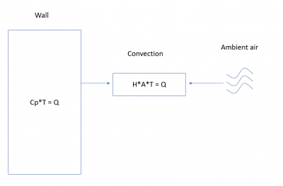
An example is a simple convection model
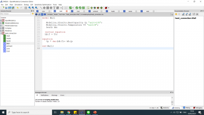
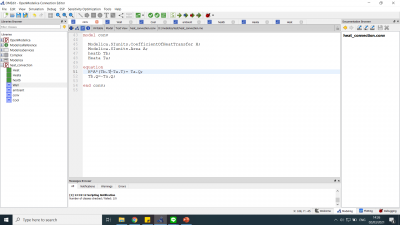
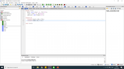
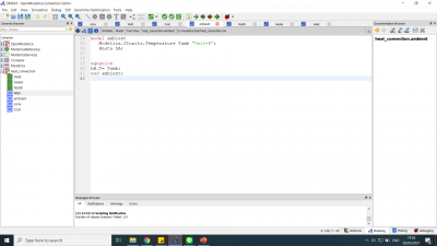
with the following text view of each model
In this meeting, we talked about the definition of system. To me, a system consists of components and/or elements that interacts among each other to form a unified function. A system is described from its boundaries and environment. One type of system that we are trying to understand is the energy conversion system. Understanding the system will be by analyzing the Bernoulli principle which can equate pressure in place of energy. A current of fluid can't be measured in mass. Thus, an alternative is marking a reference point of position in the fluid . That point will be used in determining the energy within.
6/03/2021 Saturday
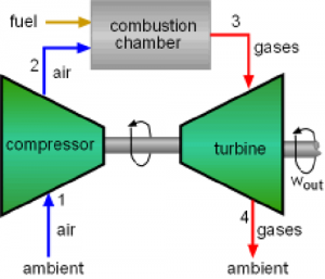
We are assigned to learn about the components and working principle of a gas turbine. A gas turbine is a combustion engine that generates its torsional energy from combusted. By pressurizing air, the force acted by it turns the turbine. The energy produced could be used in the form of electrical or mechanical. The basic components are compressor, combustion chamber, and the turbine.
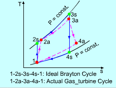
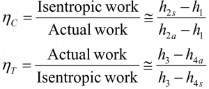
The air pressurized inside the gas turbine can be analyzed using the Brayton cycle to understand the thermodynamic process. The cycle can be analyzed using the T-s diagram. The ideal T-S diagram describes the property of air with adiabatic and isentropic processes, but the actual cycle are non-isentropic and non-adiabatic. This is caused by a pressure drop during heat exchanges and the change in entropy in the compressor and turbine. As air passes through the compressor, air gains heat, causing the temperature to rise slightly above the ideal temperature. The temperature rise will then cause entropy to increase. Entropy deviating from the ideal process can be expressed as isentropic efficiency.
6/03/2021 Saturday
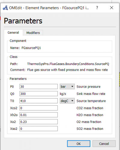
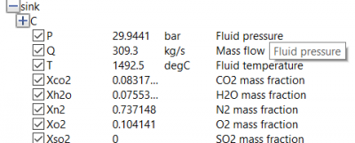
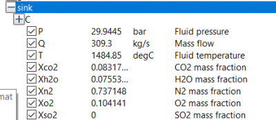
Modelica provides the comfort of visioning systems, but experiments must be made to produce better results. Hence, we are tasked in defining the relationships between parameters. I'll start by analyzing the parameter change from the input to the output. Judging from these values, it can be concluded that pressure decreases, but temperature and mass flow rate increases. Next, I'll be changing each parameters P,Q and T in the air source model.
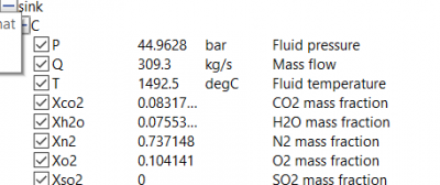
Source pressure
I experimented on increasing the source pressure to 45 bar. The result is its influence in fluid pressure.
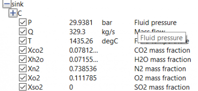
Sink mass flow rate
I experimented on increasing the source pressure to 320 kg/s. The result is its influence in pressure, flow rate, and temperature.
Air temperature
I experimented on decreasing the source pressure to 400°C. The result is its influence in pressure and temperature.
15/03/2021 Monday
As an assignment this is the link to my presentation about the open gas turbine cycle.
