Difference between revisions of "Josi Fajar Mahendra"
(Created page with " =Introduction= Hi, I'm Josi Fajar Mahendra, a Magister student at Universitas Indonesia 2024 (NPM.2406375554), and bachelor's graduate from Universitas Sriwijaya, interested...") |
(→Tugas 2) |
||
| (15 intermediate revisions by the same user not shown) | |||
| Line 2: | Line 2: | ||
=Introduction= | =Introduction= | ||
| − | Hi, I'm Josi Fajar Mahendra, | + | Hi, I'm Josi Fajar Mahendra, Magister student at Universitas Indonesia 2024 (NPM.2406375554), and bachelor's graduate from Universitas Sriwijaya, interested in energy conversion and conservation, especially in the field of fluid mechanics. |
==1. DAI5 Framework (Komputasi Teknik)== | ==1. DAI5 Framework (Komputasi Teknik)== | ||
| Line 15: | Line 15: | ||
DAI5 framework is widely applicable in engineering and technical fields, such as Finite Element Analysis (FEA), where it helps to systematically break down complex problems. By separating analysis into intentional and iterative steps, DAI5 supports efficient, detailed simulations in areas like stress, thermal, and flow analysis, making it highly suitable for structured engineering solutions. | DAI5 framework is widely applicable in engineering and technical fields, such as Finite Element Analysis (FEA), where it helps to systematically break down complex problems. By separating analysis into intentional and iterative steps, DAI5 supports efficient, detailed simulations in areas like stress, thermal, and flow analysis, making it highly suitable for structured engineering solutions. | ||
| − | ==2.Conversation With Chatgpt (Komputasi Teknik)== | + | ==2. Conversation With Chatgpt (Komputasi Teknik)== |
==Tugas 1== | ==Tugas 1== | ||
| Line 21: | Line 21: | ||
''Saya Bertanya'' :"hi chatgpt, longtime no see" | ''Saya Bertanya'' :"hi chatgpt, longtime no see" | ||
| + | |||
''ChatGPT'' : "Hi! It has been a while—great to see you! Anything new or interesting you’re working on these days?" | ''ChatGPT'' : "Hi! It has been a while—great to see you! Anything new or interesting you’re working on these days?" | ||
''Saya Bertanya'' : "Can you derive finite element equations from 1D PDE governing equations for a bacward facing step at turbo jet engine?" | ''Saya Bertanya'' : "Can you derive finite element equations from 1D PDE governing equations for a bacward facing step at turbo jet engine?" | ||
| + | |||
''ChatGPT'' : Deriving finite element equations from a 1D partial differential equation (PDE) governing flow over a backward-facing step in a turbojet engine involves several steps. Typically, this type of problem is governed by the Navier-Stokes equations in compressible or incompressible flow for boundary layers. The backward-facing step creates separation and reattachment zones due to sudden changes in geometry, which are particularly significant in fluid dynamics, especially in the design of turbojet engines. | ''ChatGPT'' : Deriving finite element equations from a 1D partial differential equation (PDE) governing flow over a backward-facing step in a turbojet engine involves several steps. Typically, this type of problem is governed by the Navier-Stokes equations in compressible or incompressible flow for boundary layers. The backward-facing step creates separation and reattachment zones due to sudden changes in geometry, which are particularly significant in fluid dynamics, especially in the design of turbojet engines. | ||
| Line 30: | Line 32: | ||
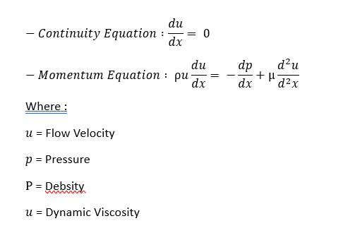
For a 1D simplified model in a turbojet engine, consider the following PDEs for steady-state, incompressible flow: | For a 1D simplified model in a turbojet engine, consider the following PDEs for steady-state, incompressible flow: | ||
| − | + | [[File:01 blog.png]] | |
| − | |||
| − | |||
| − | |||
| − | |||
| − | |||
| − | |||
| − | |||
| − | |||
In a backward-facing step problem, boundary layer effects dominate near the step, and there is often a reattachment point downstream where the flow stabilizes. | In a backward-facing step problem, boundary layer effects dominate near the step, and there is often a reattachment point downstream where the flow stabilizes. | ||
| Line 44: | Line 38: | ||
===2. Discretize the Domain=== | ===2. Discretize the Domain=== | ||
| − | In finite element analysis, divide the domain into small elements. For a 1D problem, divide the line along | + | In finite element analysis, divide the domain into small elements. For a 1D problem, divide the line along x(streamwise direction) into elements between the inlet (upstream of the step) and outlet (downstream reattachment). |
===3. Weak Formulation of the PDE=== | ===3. Weak Formulation of the PDE=== | ||
| Line 50: | Line 44: | ||
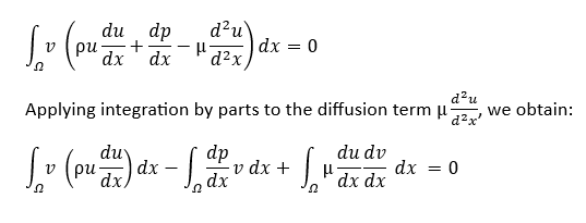
The weak form is achieved by multiplying the governing equation by a test function vvv and integrating over the domain: | The weak form is achieved by multiplying the governing equation by a test function vvv and integrating over the domain: | ||
| − | + | [[File:02 blog.png]] | |
| − | |||
| − | |||
Boundary conditions can be applied here, depending on the inlet and outlet specifications. | Boundary conditions can be applied here, depending on the inlet and outlet specifications. | ||
| Line 58: | Line 50: | ||
===4. Finite Element Approximation=== | ===4. Finite Element Approximation=== | ||
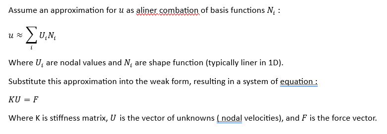
| − | + | [[File:03 blog.png]] | |
| − | |||
| − | |||
| − | |||
| − | |||
| − | |||
===5. Assembly of the Stiffness Matrix and Load Vector=== | ===5. Assembly of the Stiffness Matrix and Load Vector=== | ||
| − | + | [[File:04 blog.png]] | |
| − | |||
| − | |||
| − | |||
| − | |||
===6. Apply Boundary Conditions and Solve=== | ===6. Apply Boundary Conditions and Solve=== | ||
| − | Apply boundary conditions (inlet velocity, outlet pressure, or no-slip conditions) to reduce the system and solve for U | + | Apply boundary conditions (inlet velocity, outlet pressure, or no-slip conditions) to reduce the system and solve for '''U'''. |
===7. Post-Processing=== | ===7. Post-Processing=== | ||
| Line 85: | Line 68: | ||
==DAI5 Framework== | ==DAI5 Framework== | ||
''Saya Bertanya'' : "can you tell it using DAI5 Framework" | ''Saya Bertanya'' : "can you tell it using DAI5 Framework" | ||
| + | |||
''ChatGPT'' : Using the DAI5 Framework for deriving finite element equations from a 1D PDE governing equations for a backward-facing step in a turbojet engine can provide a structured approach. Here’s how each step of the DAI5 Framework would be applied: | ''ChatGPT'' : Using the DAI5 Framework for deriving finite element equations from a 1D PDE governing equations for a backward-facing step in a turbojet engine can provide a structured approach. Here’s how each step of the DAI5 Framework would be applied: | ||
| Line 122: | Line 106: | ||
- Evaluate results, such as the location of flow reattachment and wall shear stress, to assess the impact of the backward-facing step on the turbojet engine’s performance. | - Evaluate results, such as the location of flow reattachment and wall shear stress, to assess the impact of the backward-facing step on the turbojet engine’s performance. | ||
By following these structured steps of the DAI5 Framework, the finite element derivation process becomes organized, ensuring each phase is aligned with the final goal of understanding and optimizing flow behavior over a backward-facing step. | By following these structured steps of the DAI5 Framework, the finite element derivation process becomes organized, ensuring each phase is aligned with the final goal of understanding and optimizing flow behavior over a backward-facing step. | ||
| + | |||
| + | |||
| + | ==Tugas 2== | ||
| + | |||
| + | kali ini saya mencoba membuka diskusi dengan AI Chatgpt mengenai "Can you give a practical example (along with simple calculator such as 1D Problem) ,In engineering that continuum mechanics treatsmaterials as continuous, on integration of uninterrupted "conscious continuum" into the DAI5 framework " | ||
| + | dan meminta untuk membuat contoh terkait "the displacement distribution on a 1d rod if the heat given is heat from the bottom of the rod is evenly distributed" | ||
| + | |||
| + | ''Saya Bertanya'' :"hi chatgpt, Can you give a practical example (along with simple calculator such as 1D Problem) ,In engineering that continuum mechanics treatsmaterials as continuous, on integration of uninterrupted "conscious continuum" into the DAI5 framework" | ||
| + | |||
| + | ''ChatGPT'' : Sure, let's look at a practical example of continuum mechanics in the context of a 1-dimensional engineering problem, illustrating how materials can be treated as continuous and integrated with concepts like uninterrupted "conscious continuum" in a computational or theoretical framework such as Distributed Artificial Intelligence (DAI5). | ||
| + | |||
| + | '''Background: Continuum Mechanics''' | ||
| + | |||
| + | In continuum mechanics, materials are considered continuous, meaning we ignore the discrete atomic or molecular structure of matter and treat it as if it were smoothly distributed. This simplification allows us to use mathematical models (often differential equations) to describe properties like stress, strain, and deformation under external forces. | ||
| + | |||
| + | '''Practical Example: 1D Bar Under Tension''' | ||
| + | |||
| + | consider a steel bar of length 1 m and cross section area 0,01 under tensile load of 1000 N . we found | ||
| + | |||
| + | 1. '''Strees''' on bar. | ||
| + | 2. '''Strain''' experienced by the bar. | ||
| + | 3, '''Displacement''' at bar's end. | ||
| + | |||
| + | in this problem, we assume: | ||
| + | - the bar behaves as continous material. | ||
| + | - Material properties (E) | ||
| + | |||
| + | Using '''continuum mechanics approach''', we treat the bar as a continous element and apply simple 1D stress-strain relations | ||
| + | |||
| + | [[File:21 blog.png]] | ||
| + | |||
| + | [[File:22 blog.png]] | ||
| + | |||
| + | [[File:23 blog.png]] | ||
| + | |||
| + | '''Integrating with DAI5 Framework and "Conscious Continuum"''' | ||
| + | |||
| + | In the DAI5 framework, this continuum can be enhanced by integrating sensors and actuators within the bar, coupled with AI that perceives and responds to minute changes in stress and strain, creating an "intelligent" material. This makes it a part of a "conscious continuum," where each element of the material has embedded "awareness" of its stress state and can communicate it in real time. | ||
| + | |||
| + | |||
| + | For example, in a high-stress scenario, embedded sensors might detect stress exceeding a certain threshold and signal an AI system to redistribute load or apply reinforcement. This can extend beyond individual sensors to a network that communicates material health continuously, embodying the "conscious" aspect of material. | ||
| + | |||
| + | '''Summary''' | ||
| + | |||
| + | |||
| + | This example demonstrates a basic 1D continuum mechanics problem where: | ||
| + | |||
| + | 1. The bar is treated as continuous. | ||
| + | |||
| + | 2. Stress, strain, and displacement are calculated. | ||
| + | |||
| + | 3. DAI5 could facilitate a "conscious continuum" where material state awareness is distributed for real-time monitoring and adaptability, crucial in smart engineering structures. | ||
| + | |||
| + | ''Saya Bertanya'' : Can you solve the displacement distribution on a 1d rod if the heat given is heat from the bottom of the rod is evenly distributed heat using computational methods and make the coding in python using FEM Method following the assume before | ||
| + | |||
| + | ''ChatGPT'' : To solve the displacement distribution on a 1D rod with a uniformly distributed heat source at its bottom, we can use the Finite Element Method (FEM). Here’s a breakdown of the problem setup and how to implement it in Python. | ||
| + | |||
| + | |||
| + | '''Problem Setup''' | ||
| + | |||
| + | We have a rod of length L, and heat is applied at the bottom, causing a temperature increase that induces thermal expansion. The displacement along the rod can be modeled based on this thermal expansion. | ||
| + | |||
| + | |||
| + | Assumptions | ||
| + | 1. 1D rod: The rod is along the x-axis. | ||
| + | 2. Uniform heat distribution: The heat is evenly distributed along the bottom of the rod, causing uniform temperature distribution. | ||
| + | 3. Material properties: Young’s modulus E, coefficient of thermal expansion α, and temperature increase ΔT are known and constant. | ||
| + | 4. Boundary Conditions: Fixed end at x=0 (displacement = 0) and free end at x=L | ||
| + | |||
| + | [[File:24 blog.png]] | ||
| + | |||
| + | '''Python Implementation Using FEM''' | ||
| + | |||
| + | Here’s how to set up and solve this problem using the FEM approach in Python. | ||
| + | |||
| + | [[File:25 blog.png]] | ||
| + | |||
| + | '''Explanation of the Code''' | ||
| + | |||
| + | 1. Material Properties and Setup: We define the material properties (Young’s modulus, thermal expansion coefficient) and setup the rod's length and the number of elements. | ||
| + | |||
| + | 2. Stiffness Matrix Assembly: For each element, we calculate the local stiffness matrix and assemble it into the global stiffness matrix K. | ||
| + | |||
| + | 3. Thermal Load Vector: We populate the thermal load vector F using the thermal expansion effect, which is applied as a load due to temperature rise. | ||
| + | |||
| + | 4. Boundary Conditions: We apply the boundary condition (fixed end at x=0), reducing the system size by removing the fixed displacement row and column. | ||
| + | |||
| + | 5. Solution: We solve for the nodal displacements U. | ||
| + | |||
| + | 6. Plotting: Finally, we plot the FEM solution and compare it with the analytical solution u(x)=αΔT⋅x. | ||
| + | |||
| + | '''Expected Output''' | ||
| + | |||
| + | The plot will show the displacement distribution along the rod due to uniform heating, with the FEM solution closely matching the analytical solution. The displacement will increase linearly along the rod due to the uniform expansion caused by the temperature increase. | ||
Revision as of 19:40, 11 November 2024
Contents
Introduction
Hi, I'm Josi Fajar Mahendra, Magister student at Universitas Indonesia 2024 (NPM.2406375554), and bachelor's graduate from Universitas Sriwijaya, interested in energy conversion and conservation, especially in the field of fluid mechanics.
1. DAI5 Framework (Komputasi Teknik)
“DAI5 Framework” adalah kerangka berpikiryang dikembangkan oleh Dr. Ahmad Indra Siswantara, dengan menggunakan conscious thinking (kesadaran berpikir) sebagai basis kerangka berfikir. Dengan kalimat “ My Heart work to encode (menulis/membuat suatu program) and My Brain decodes(mengeksekusi program)". terdapat 4 kunci yaitu Intention, Initial Thinking (about the problem), Idealization, Instruction Set. dengan DAI5 memadukan heartware & brainware Adapun makna dari setiap kata kunci adalah sebagai berikut: 1. Intention (Niat) – Memulai setiap langkah dengan niat yang kokoh serta tujuan yang jelas yang ingin diraih. 2. Initial Thinking (Pemikiran Awal) – Melakukan peninjauan awal untuk memahami konteks atau masalah sebelum memulai tindakan.. 3. Idealization (Idealasi) – Membayangkan solusi atau pendekatan yang optimal untuk mengatasi sebuah masalah. 4. Instruction Set (Instruksi) – Menguraikan proses menjadi langkah-langkah terstruktur dan sistematis untuk memudahkan pelaksanaan.
DAI5 framework is widely applicable in engineering and technical fields, such as Finite Element Analysis (FEA), where it helps to systematically break down complex problems. By separating analysis into intentional and iterative steps, DAI5 supports efficient, detailed simulations in areas like stress, thermal, and flow analysis, making it highly suitable for structured engineering solutions.
2. Conversation With Chatgpt (Komputasi Teknik)
Tugas 1
kali ini saya mencoba membuka diskusi dengan AI Chatgpt mengenai "Can you derive finite element equations from 1D PDE governing equations for a bacward facing step at turbo jet engine? "
Saya Bertanya :"hi chatgpt, longtime no see"
ChatGPT : "Hi! It has been a while—great to see you! Anything new or interesting you’re working on these days?"
Saya Bertanya : "Can you derive finite element equations from 1D PDE governing equations for a bacward facing step at turbo jet engine?"
ChatGPT : Deriving finite element equations from a 1D partial differential equation (PDE) governing flow over a backward-facing step in a turbojet engine involves several steps. Typically, this type of problem is governed by the Navier-Stokes equations in compressible or incompressible flow for boundary layers. The backward-facing step creates separation and reattachment zones due to sudden changes in geometry, which are particularly significant in fluid dynamics, especially in the design of turbojet engines.
1. Define the Governing Equations
For a 1D simplified model in a turbojet engine, consider the following PDEs for steady-state, incompressible flow:
In a backward-facing step problem, boundary layer effects dominate near the step, and there is often a reattachment point downstream where the flow stabilizes.
2. Discretize the Domain
In finite element analysis, divide the domain into small elements. For a 1D problem, divide the line along x(streamwise direction) into elements between the inlet (upstream of the step) and outlet (downstream reattachment).
3. Weak Formulation of the PDE
The weak form is achieved by multiplying the governing equation by a test function vvv and integrating over the domain:
Boundary conditions can be applied here, depending on the inlet and outlet specifications.
4. Finite Element Approximation
5. Assembly of the Stiffness Matrix and Load Vector
6. Apply Boundary Conditions and Solve
Apply boundary conditions (inlet velocity, outlet pressure, or no-slip conditions) to reduce the system and solve for U.
7. Post-Processing
After solving, calculate secondary quantities like vorticity, reattachment length, and wall shear stress to assess the impact of the backward-facing step on the flow characteristics within the turbojet engine.
This approach provides a basis for finite element analysis of flow over complex geometries in turbojets, where accurate predictions of recirculation and separation are essential for performance evaluation and design improvement.
DAI5 Framework
Saya Bertanya : "can you tell it using DAI5 Framework"
ChatGPT : Using the DAI5 Framework for deriving finite element equations from a 1D PDE governing equations for a backward-facing step in a turbojet engine can provide a structured approach. Here’s how each step of the DAI5 Framework would be applied:
1. Intention: Define the Purpose
In this step, clarify why we’re deriving the finite element equations. The main goal here is to analyze the flow characteristics over a backward-facing step in a turbojet engine, focusing on velocity profiles, pressure distribution, and recirculation zones that result from the sudden expansion in geometry. Understanding these characteristics can lead to improved designs by minimizing drag and optimizing engine efficiency.
2. Initial Thinking: Explore Assumptions and Requirements
At this stage, brainstorm the requirements and assumptions necessary to simplify the problem. For a turbojet application:
- Governing Equations: Start with the 1D incompressible Navier-Stokes equations or continuity and momentum equations as simplified models.
- Boundary Conditions: Consider boundary conditions such as inlet velocity, outlet pressure, and no-slip wall conditions at the backward-facing step.
- Discretization Approach: Plan to divide the computational domain into elements along the streamwise xxx-direction and use a finite element approximation with shape functions for velocity and pressure.
- Assumptions: Assume steady-state flow, incompressibility, and a simplified 1D flow model to manage computational complexity.
3. Idealization: Conceptualize the Desired Outcome
In this phase, envision the ideal outcome and how the derived equations will enable analysis:
- The finite element formulation should provide an accurate representation of flow separation, reattachment zones, and recirculation caused by the backward-facing step.
- The ideal solution would capture the effects of turbulence near the step, but in this simplified model, focus on primary flow characteristics like velocity and pressure gradients along the domain.
- Aim for a stable and computationally efficient solution that can later be extended to more complex, multi-dimensional models if required.
4. Instruction Set: Develop Steps for Derivation
Here, break down the derivation process into actionable steps, which can later be implemented in software:
- Formulate the Weak Form: Multiply each governing equation by a test function and integrate over the domain. Use integration by parts to handle higher-order derivatives, which will result in terms suitable for the finite element approach.
- Select Shape Functions: Choose appropriate shape functions for the element discretization, which could be linear or quadratic in 1D. These shape functions will approximate the velocity and pressure fields.
- Assemble System of Equations: For each element, derive the local stiffness matrix and force vector by evaluating integrals of the convective, diffusive, and pressure terms. Then assemble these into the global matrix.
- Apply Boundary Conditions: Incorporate boundary conditions (e.g., velocity at the inlet and outlet conditions) to refine the system for solvability.
- Solve the System: Solve the assembled finite element equations to get the nodal values of velocity and pressure.
5. Implementation: Execute the Derivation
Finally, implement the derivation and computation:
- Write or run the derived finite element equations using a suitable computational tool (e.g., MATLAB, ANSYS, or Python with FEA libraries).
- Validate the results by comparing the velocity and pressure profiles with known solutions or benchmark cases of flow over a backward-facing step.
- Evaluate results, such as the location of flow reattachment and wall shear stress, to assess the impact of the backward-facing step on the turbojet engine’s performance.
By following these structured steps of the DAI5 Framework, the finite element derivation process becomes organized, ensuring each phase is aligned with the final goal of understanding and optimizing flow behavior over a backward-facing step.
Tugas 2
kali ini saya mencoba membuka diskusi dengan AI Chatgpt mengenai "Can you give a practical example (along with simple calculator such as 1D Problem) ,In engineering that continuum mechanics treatsmaterials as continuous, on integration of uninterrupted "conscious continuum" into the DAI5 framework " dan meminta untuk membuat contoh terkait "the displacement distribution on a 1d rod if the heat given is heat from the bottom of the rod is evenly distributed"
Saya Bertanya :"hi chatgpt, Can you give a practical example (along with simple calculator such as 1D Problem) ,In engineering that continuum mechanics treatsmaterials as continuous, on integration of uninterrupted "conscious continuum" into the DAI5 framework"
ChatGPT : Sure, let's look at a practical example of continuum mechanics in the context of a 1-dimensional engineering problem, illustrating how materials can be treated as continuous and integrated with concepts like uninterrupted "conscious continuum" in a computational or theoretical framework such as Distributed Artificial Intelligence (DAI5).
Background: Continuum Mechanics
In continuum mechanics, materials are considered continuous, meaning we ignore the discrete atomic or molecular structure of matter and treat it as if it were smoothly distributed. This simplification allows us to use mathematical models (often differential equations) to describe properties like stress, strain, and deformation under external forces.
Practical Example: 1D Bar Under Tension
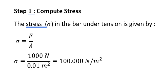
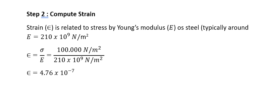
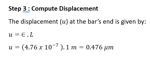
consider a steel bar of length 1 m and cross section area 0,01 under tensile load of 1000 N . we found
1. Strees on bar. 2. Strain experienced by the bar. 3, Displacement at bar's end.
in this problem, we assume: - the bar behaves as continous material. - Material properties (E)
Using continuum mechanics approach, we treat the bar as a continous element and apply simple 1D stress-strain relations
Integrating with DAI5 Framework and "Conscious Continuum"
In the DAI5 framework, this continuum can be enhanced by integrating sensors and actuators within the bar, coupled with AI that perceives and responds to minute changes in stress and strain, creating an "intelligent" material. This makes it a part of a "conscious continuum," where each element of the material has embedded "awareness" of its stress state and can communicate it in real time.
For example, in a high-stress scenario, embedded sensors might detect stress exceeding a certain threshold and signal an AI system to redistribute load or apply reinforcement. This can extend beyond individual sensors to a network that communicates material health continuously, embodying the "conscious" aspect of material.
Summary
This example demonstrates a basic 1D continuum mechanics problem where:
1. The bar is treated as continuous.
2. Stress, strain, and displacement are calculated.
3. DAI5 could facilitate a "conscious continuum" where material state awareness is distributed for real-time monitoring and adaptability, crucial in smart engineering structures.
Saya Bertanya : Can you solve the displacement distribution on a 1d rod if the heat given is heat from the bottom of the rod is evenly distributed heat using computational methods and make the coding in python using FEM Method following the assume before
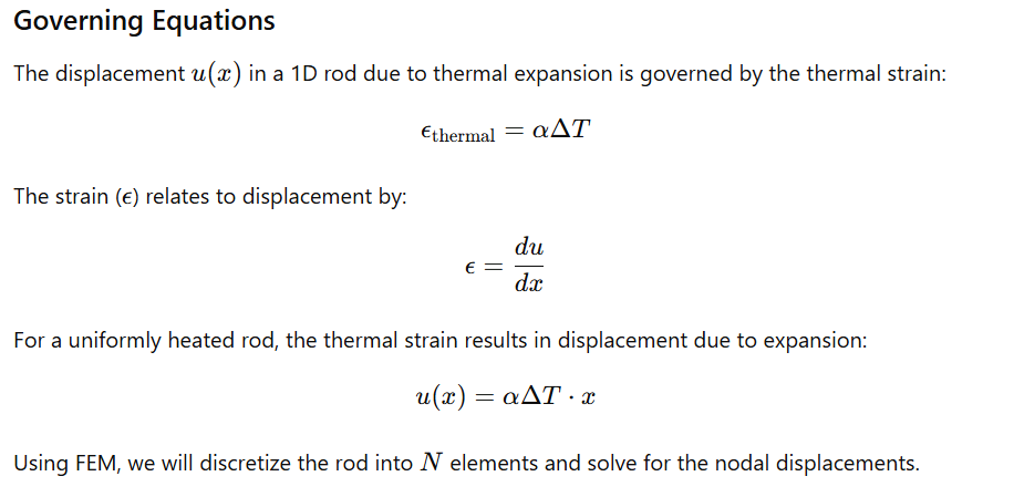
ChatGPT : To solve the displacement distribution on a 1D rod with a uniformly distributed heat source at its bottom, we can use the Finite Element Method (FEM). Here’s a breakdown of the problem setup and how to implement it in Python.
Problem Setup
We have a rod of length L, and heat is applied at the bottom, causing a temperature increase that induces thermal expansion. The displacement along the rod can be modeled based on this thermal expansion.
Assumptions
1. 1D rod: The rod is along the x-axis.
2. Uniform heat distribution: The heat is evenly distributed along the bottom of the rod, causing uniform temperature distribution.
3. Material properties: Young’s modulus E, coefficient of thermal expansion α, and temperature increase ΔT are known and constant.
4. Boundary Conditions: Fixed end at x=0 (displacement = 0) and free end at x=L
Python Implementation Using FEM
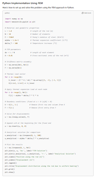
Here’s how to set up and solve this problem using the FEM approach in Python.
Explanation of the Code
1. Material Properties and Setup: We define the material properties (Young’s modulus, thermal expansion coefficient) and setup the rod's length and the number of elements.
2. Stiffness Matrix Assembly: For each element, we calculate the local stiffness matrix and assemble it into the global stiffness matrix K.
3. Thermal Load Vector: We populate the thermal load vector F using the thermal expansion effect, which is applied as a load due to temperature rise.
4. Boundary Conditions: We apply the boundary condition (fixed end at x=0), reducing the system size by removing the fixed displacement row and column.
5. Solution: We solve for the nodal displacements U.
6. Plotting: Finally, we plot the FEM solution and compare it with the analytical solution u(x)=αΔT⋅x.
Expected Output
The plot will show the displacement distribution along the rod due to uniform heating, with the FEM solution closely matching the analytical solution. The displacement will increase linearly along the rod due to the uniform expansion caused by the temperature increase.
